
Page 114 - Engineered Interfaces in Fiber Reinforced Composites
P. 114
Chapter 4. Micromechanics of stress transfer 91
4.2.2. Early shear-lag models
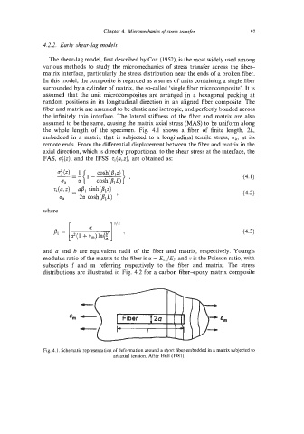
The shear-lag model, first described by Cox (1952), is the most widely used among
various methods to study the micromechanics of stress transfer across the fiber-
matrix interface, particularly the stress distribution near the ends of a broken fiber.
In this model, the composite is regarded as a series of units containing a single fiber
surrounded by a cylinder of matrix, the so-called ‘single fiber microcomposite’. It is
assumed that the unit microcomposites are arranged in a hexagonal packing at
random positions in its longitudinal direction in an aligned fiber composite. The
fiber and matrix are assumed to be elastic and isotropic, and perfectly bonded across
the infinitely thin interface. The lateral stiffness of the fiber and matrix are also
assumed to be the same, causing the matrix axial stress (MAS) to be uniform along
the whole length of the specimen. Fig. 4.1 shows a fiber of finite length, 2L,
embedded in a matrix that is subjected to a longitudinal tensile stress, bay at its
remote ends. From the differential displacement between the fiber and matrix in the
axial direction, which is directly proportional to the shear stress at the interface, the
FAS, (izf(z), and the IFSS, q(a,z), are obtained as:
where
r 1112
and a and b are equivalent radii of the fiber and matrix, respectively. Young’s
modulus ratio of the matrix to the fiber is a = E,/Ef, and v is the Poisson ratio, with
subscripts f and m referring respectively to the fiber and matrix. The stress
distributions are illustrated in Fig. 4.2 for a carbon fiber-epoxy matrix composite
Em
Fig. 4.1, Schematic representation of deformation around a short fiber embedded in a matrix subjected to
an axial tension. After Hull (1981).