
Page 118 - Engineered Interfaces in Fiber Reinforced Composites
P. 118
Chapter 4. Micromechanics of stress transfer 101
matrix, 1 /a. Clearly, the ineffective length varies inversely proportionally to in
this early model. A detailed discussion regarding the influence of the properties of
composite constituents on the critical transfer length is given in Section 3.2.3.
4.2.3. An improved model based on a fracture mechanics approach
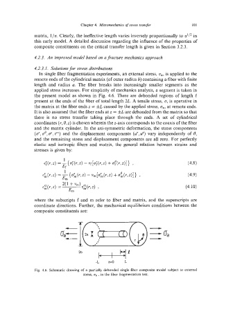
4.2.3.1. Solutions for stress distributions
In single fiber fragmentation experiments, an external stress, a,, is applied to the
remote ends of the cylindrical matrix (of outer radius b) containing a fiber with finite
length and radius a. The fiber breaks into increasingly smaller segments as the
applied stress increases. For simplicity of mechanics analysis, a segment is taken in
the present model as shown in Fig. 4.6. There are debonded regions of length C
present at the ends of the fiber of total length 2L. A tensile stress, 0, is operative in
the matrix at the fiber ends z = fL caused by the applied stress, ga, at remote ends.
It is also assumed that the fiber ends at z = fL are debonded from the matrix so that
there is no stress transfer taking place through the ends. A set of cylindrical
coordinates (Y, 6, z) is chosen wherein the z-axis corresponds to the coaxis of the fiber
and the matrix cylinder. In the axi-symmetric deformation, the stress components
(6, a@, o', z") and the displacement components (d, 2) vary independently of 6,
and the remaining stress and displacement components are all zero. For perfectly
elastic and isotropic fibers and matrix, the general relation between strains and
stresses is given by:
(4.8)
(4.9)
(4.10)
where the subscripts f and m refer to fiber and matrix, and the superscripts are
coordinate directions. Further, the mechanical equilibrium conditions between the
composite constituents are:
c-
-L z=o L
Fig. 4.6. Schematic drawing of a partially debonded single fiber composite model subject to external
stress, ua , in the fiber fragmentation test.