
Page 63 - Engineered Interfaces in Fiber Reinforced Composites
P. 63
46 Engineered interfaces in fiber reinforced composites
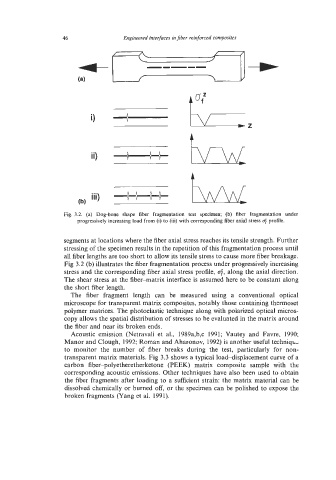
Fig. 3.2. (a) Dog-bone shape fiber fragmentation test specimen; (b) fiber fragmentation under
progressively increasing load from (i) to (iii) with corresponding fiber axial stress c$ profile.
segments at locations where the fiber axial stress reaches its tensile strength. Further
stressing of the specimen results in the repetition of this fragmentation process until
all fiber lengths are too short to allow its tensile stress to cause more fiber breakage.
Fig 3.2 (b) illustrates the fiber fragmentation process under progressively increasing
stress and the corresponding fiber axial stress profile, 6, along the axial direction.
The shear stress at the fiber-matrix interface is assumed here to be constant along
the short fiber length.
The fiber fragment length can be measured using a conventional optical
microscope for transparent matrix composites, notably those containing thermoset
polymer matrices. The photoelastic technique along with polarized optical micros-
copy allows the spatial distribution of stresses to be evaluated in the matrix around
the fiber and near its broken ends.
Acoustic emission (Netravali et al., 1989a,b,c 1991; Vautey and Favre, 1990;
Manor and Clough, 1992; Roman and Aharonov, 1992) is another useful techniqL,
to monitor the number of fiber breaks during the test, particularly for non-
transparent matrix materials. Fig 3.3 shows a typical loaddisplacement curve of a
carbon fiber-polyetheretherketone (PEEK) matrix composite sample with the
corresponding acoustic emissions. Other techniques have also been used to obtain
the fiber fragments after loading to a sufficient strain: the matrix material can be
dissolved chemically or burned off, or the specimen can be polished to expose the
broken fragments (Yang et al. 1991).