
Page 381 - Engineering Electromagnetics, 8th Edition
P. 381
CHAPTER 10 Transmission Lines 363
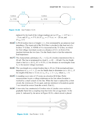
Figure 10.33 See Problem 10.24.
replaced by the load) if the voltage readings are (a) |V | max = 12Vat z =
−5 cm, and |V | min = 5V;(b) |V | max = 17Vat z =−20 cm, and
|V | min = 0.
10.26 A 50- lossless line is of length 1.1 λ.Itis terminated by an unknown load
impedance. The input end of the 50- line is attached to the load end of a
lossless 75- line. A VSWR of 4 is measured on the 75- line, on which
the first voltage maximum occurs at a distance of 0.2 λ in front of the
junction between the two lines. Use the Smith chart to find the unknown
load impedance.
10.27 The characteristic admittance (Y 0 = 1/Z 0 )ofa lossless transmission line is
20 mS. The line is terminated in a load Y L = 40 − j20 mS. Use the Smith
chart to find (a) s;(b) Y in if l = 0.15λ;(c) the distance in wavelengths from
Y L to the nearest voltage maximum.
10.28 The wavelength on a certain lossless line is 10 cm. If the normalized input
impedance is z in = 1 + j2, use the Smith chart to determine (a) s;(b) z L ,if
the length of the line is 12 cm; (c) x L ,if z L = 2 + jx L where x L > 0.
10.29 A standing wave ratio of 2.5 exists on a lossless 60 line. Probe
measurements locate a voltage minimum on the line whose location is
marked by a small scratch on the line. When the load is replaced by a short
circuit, the minima are 25 cm apart, and one minimum is located at a point
7cmtoward the source from the scratch. Find Z L .
10.30 Atwo-wire line constructed of lossless wire of circular cross section is
gradually flared into a coupling loop that looks like an egg beater. At the
point X, indicated by the arrow in Figure 10.34, a short circuit is placed
Figure 10.34 See Problem 10.30.