Page 384 - Engineering Electromagnetics, 8th Edition
P. 384

366                ENGINEERING ELECTROMAGNETICS


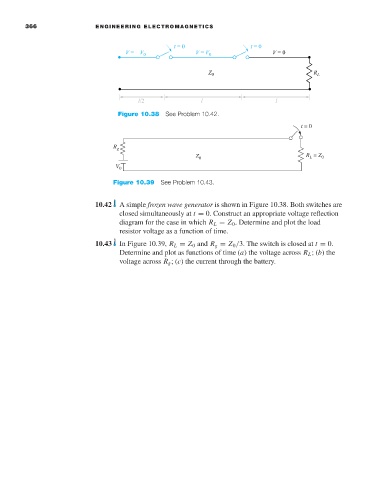
                                           Figure 10.38 See Problem 10.42.
                                                                                             t = 0


                                          R g
                                                                Z 0                           R  = Z 0
                                                                                               L
                                          V 0
                                          Figure 10.39 See Problem 10.43.


                                     10.42  A simple frozen wave generator is shown in Figure 10.38. Both switches are
                                           closed simultaneously at t = 0. Construct an appropriate voltage reflection
                                           diagram for the case in which R L = Z 0 . Determine and plot the load
                                           resistor voltage as a function of time.
                                     10.43  In Figure 10.39, R L = Z 0 and R g = Z 0 /3. The switch is closed at t = 0.
                                           Determine and plot as functions of time (a) the voltage across R L ;(b) the
                                           voltage across R g ;(c) the current through the battery.
   379   380   381   382   383   384   385   386   387   388   389