
Page 473 - Engineering Electromagnetics, 8th Edition
P. 473
CHAPTER 13 Guided Waves 455
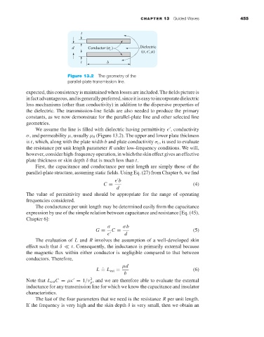
Figure 13.2 The geometry of the
parallel-plate transmission line.
expected, this consistency is maintained when losses are included. The fields picture is
infactadvantageous,andisgenerallypreferred,sinceitiseasytoincorporatedielectric
loss mechanisms (other than conductivity) in addition to the dispersive properties of
the dielectric. The transmission-line fields are also needed to produce the primary
constants, as we now demonstrate for the parallel-plate line and other selected line
geometries.
We assume the line is filled with dielectric having permittivity , conductivity
σ, and permeability µ, usually µ 0 (Figure 13.2). The upper and lower plate thickness
is t, which, along with the plate width b and plate conductivity σ c ,is used to evaluate
the resistance per unit length parameter R under low-frequency conditions. We will,
however, consider high-frequency operation, in which the skin effect gives an effective
plate thickness or skin depth δ that is much less than t.
First, the capacitance and conductance per unit length are simply those of the
parallel-plate structure, assuming static fields. Using Eq. (27) from Chapter 6, we find
b
C = (4)
d
The value of permittivity used should be appropriate for the range of operating
frequencies considered.
The conductance per unit length may be determined easily from the capacitance
expression by use of the simple relation between capacitance and resistance [Eq. (45),
Chapter 6]:
σ σb
G = C = (5)
d
The evaluation of L and R involves the assumption of a well-developed skin
effect such that δ t. Consequently, the inductance is primarily external because
the magnetic flux within either conductor is negligible compared to that between
conductors. Therefore,
. µd
L = L ext = (6)
b
2
Note that L ext C = µ = 1/ν , and we are therefore able to evaluate the external
p
inductance for any transmission line for which we know the capacitance and insulator
characteristics.
The last of the four parameters that we need is the resistance R per unit length.
If the frequency is very high and the skin depth δ is very small, then we obtain an