
Page 474 - Engineering Electromagnetics, 8th Edition
P. 474
456 ENGINEERING ELECTROMAGNETICS
appropriate expression for R by distributing the total current uniformly throughout
a depth δ. The skin effect resistance (through both conductors in series over a unit
length) is
2
R = (7)
σ c δb
Finally, it is convenient to include the common expression for the characteristic
impedance of the line here with the parameter formulas:
L ext µ d
Z 0 = = (8)
C b
If necessary, a more accurate value may be obtained from Eq. (47), Chapter 10. Note
that when substituting (8) into (2b), and using (2a), we obtain the expected relation
√
for a TEM wave, E xs = ηH ys , where η = µ/ .
D13.1. Parameters for the planar transmission line shown in Figure 13.2 are
b = 6 mm, d = 0.25 mm, t = 25 mm, σ c = 5.5 × 10 S/m, = 25 pF/m,
7
µ = µ 0 , and σ/ω = 0.03. If the operating frequency is 750 MHz, calculate:
(a) α;(b) β;(c) Z 0 .
Ans. 0.47 Np/m; 26 rad/m; 9.3 0.7
◦
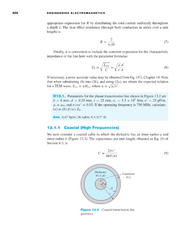
13.1.1 Coaxial (High Frequencies)
We next consider a coaxial cable in which the dielectric has an inner radius a and
outer radius b (Figure 13.3). The capacitance per unit length, obtained as Eq. (5) of
Section 6.3, is
2π
C = (9)
ln(b/a)
Figure 13.3 Coaxial transmission-line
geometry.