
Page 479 - Engineering Electromagnetics, 8th Edition
P. 479
CHAPTER 13 Guided Waves 461
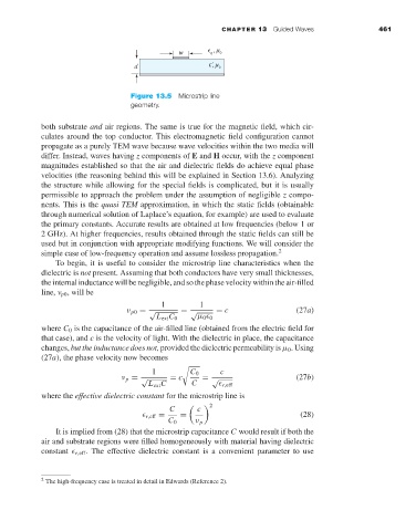
Figure 13.5 Microstrip line
geometry.
both substrate and air regions. The same is true for the magnetic field, which cir-
culates around the top conductor. This electromagnetic field configuration cannot
propagate as a purely TEM wave because wave velocities within the two media will
differ. Instead, waves having z components of E and H occur, with the z component
magnitudes established so that the air and dielectric fields do achieve equal phase
velocities (the reasoning behind this will be explained in Section 13.6). Analyzing
the structure while allowing for the special fields is complicated, but it is usually
permissible to approach the problem under the assumption of negligible z compo-
nents. This is the quasi TEM approximation, in which the static fields (obtainable
through numerical solution of Laplace’s equation, for example) are used to evaluate
the primary constants. Accurate results are obtained at low frequencies (below 1 or
2 GHz). At higher frequencies, results obtained through the static fields can still be
used but in conjunction with appropriate modifying functions. We will consider the
simple case of low-frequency operation and assume lossless propagation. 2
To begin, it is useful to consider the microstrip line characteristics when the
dielectric is not present. Assuming that both conductors have very small thicknesses,
the internal inductance will be negligible, and so the phase velocity within the air-filled
line, ν p0 , will be
1 1
ν p0 = √ = √ = c (27a)
L ext C 0 µ 0 0
where C 0 is the capacitance of the air-filled line (obtained from the electric field for
that case), and c is the velocity of light. With the dielectric in place, the capacitance
changes, but the inductance does not, provided the dielectric permeability is µ 0 . Using
(27a), the phase velocity now becomes
1 C 0 c
ν p = √ = c = √ (27b)
L ext C C r,eff
where the effective dielectric constant for the microstrip line is
C c 2
r,eff = = (28)
C 0 ν p
It is implied from (28) that the microstrip capacitance C would result if both the
air and substrate regions were filled homogeneously with material having dielectric
constant r,eff . The effective dielectric constant is a convenient parameter to use
2 The high-frequency case is treated in detail in Edwards (Reference 2).