
Page 481 - Engineering Electromagnetics, 8th Edition
P. 481
CHAPTER 13 Guided Waves 463
D13.4. Amicrostriplineisfabricatedonalithiumniobatesubstrate( r = 4.8)
of1mmthickness.Ifthetopconductoris2mmwide,find(a) r,eff ;(b) Z 0 ;(c)ν p .
8
Ans. 3.6; 47 ;1.6 × 10 m/s
13.2 BASIC WAVEGUIDE OPERATION
Waveguides assume many different forms that depend on the purpose of the guide
and on the frequency of the waves to be transmitted. The simplest form (in terms of
analysis) is the parallel-plate guide shown in Figure 13.6. Other forms are the hollow-
pipe guides, including the rectangular waveguide of Figure 13.7, and the cylindrical
guide, shown in Figure 13.8. Dielectric waveguides, used primarily at optical fre-
quencies, include the slab waveguide of Figure 13.9 and the optical fiber, shown in
Figure 13.10. Each of these structures possesses certain advantages over the others,
depending on the application and the frequency of the waves to be transmitted. All
guides, however, exhibit the same basic operating principles, which we will explore
in this section.
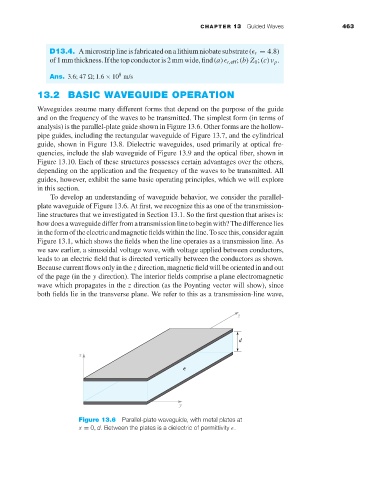
To develop an understanding of waveguide behavior, we consider the parallel-
plate waveguide of Figure 13.6. At first, we recognize this as one of the transmission-
line structures that we investigated in Section 13.1. So the first question that arises is:
howdoesawaveguidedifferfromatransmissionlinetobeginwith?Thedifferencelies
intheformoftheelectricandmagneticfieldswithintheline.Toseethis,consideragain
Figure 13.1, which shows the fields when the line operates as a transmission line. As
we saw earlier, a sinusoidal voltage wave, with voltage applied between conductors,
leads to an electric field that is directed vertically between the conductors as shown.
Because current flows only in the z direction, magnetic field will be oriented in and out
of the page (in the y direction). The interior fields comprise a plane electromagnetic
wave which propagates in the z direction (as the Poynting vector will show), since
both fields lie in the transverse plane. We refer to this as a transmission-line wave,
Figure 13.6 Parallel-plate waveguide, with metal plates at
x = 0, d. Between the plates is a dielectric of permittivity .