
Page 485 - Engineering Electromagnetics, 8th Edition
P. 485
CHAPTER 13 Guided Waves 467
13.3 PLANE WAVE ANALYSIS OF THE
PARALLEL-PLATE WAVEGUIDE
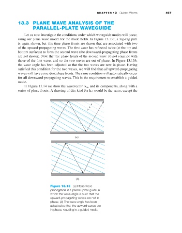
Let us now investigate the conditions under which waveguide modes will occur,
using our plane wave model for the mode fields. In Figure 13.13a,a zig-zag path
is again shown, but this time phase fronts are drawn that are associated with two
of the upward-propagating waves. The first wave has reflected twice (at the top and
bottom surfaces) to form the second wave (the downward-propagating phase fronts
are not shown). Note that the phase fronts of the second wave do not coincide with
those of the first wave, and so the two waves are out of phase. In Figure 13.13b,
the wave angle has been adjusted so that the two waves are now in phase. Having
satisfied this condition for the two waves, we will find that all upward-propagating
waves will have coincident phase fronts. The same condition will automatically occur
for all downward-propagating waves. This is the requirement to establish a guided
mode.
In Figure 13.14 we show the wavevector, k u , and its components, along with a
series of phase fronts. A drawing of this kind for k d would be the same, except the
Figure 13.13 (a) Plane wave
propagation in a parallel-plate guide in
which the wave angle is such that the
upward-propagating waves are not in
phase. (b) The wave angle has been
adjusted so that the upward waves are
in phase, resulting in a guided mode.