Page 487 - Engineering Electromagnetics, 8th Edition
P. 487
CHAPTER 13   Guided Waves              469

                     which we express either in terms of the dielectric constant,   ,or the refractive index,

                                                                    r
                     n,of the medium.
                         It is κ m , the x component of k u and k d , that will be useful to us in quantifying
                     our requirement on coincident phase fronts through a condition known as transverse
                     resonance. This condition states that the net phase shift measured during a round trip
                     over the full transverse dimension of the guide must be an integer multiple of 2π
                     radians. This is another way of stating that all upward- (or downward-) propagating
                     plane waves must have coincident phases. The various segments of this round trip are
                     illustrated in Figure 13.15. We assume for this exercise that the waves are frozen in
                     time and that an observer moves vertically over the round trip, measuring phase shift
                     along the way. In the first segment (Figure 13.15a), the observer starts at a position
                     just above the lower conductor and moves vertically to the top conductor through
                     distance d. The measured phase shift over this distance is κ m d rad. On reaching the
                     top surface, the observer will note a possible phase shift on reflection (Figure 13.15b).
                     This will be π if the wave is TE polarized and will be zero if the wave is TM polarized
                     (see Figure 13.16 for a demonstration of this). Next, the observer moves along the
                     reflected wave phases down to the lower conductor and again measures a phase shift
                     of κ m d (Figure 13.15c). Finally, after including the phase shift on reflection at the
                     bottom conductor, the observer is back at the original starting point and is noting the
                     phase of the next upward-propagating wave.
                         The total phase shift over the round trip is required to be an integer multiple
                     of 2π:

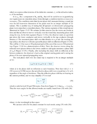
                                           κ m d + φ + κ m d + φ = 2mπ               (37)

                     where φ is the phase shift on reflection at each boundary. Note that with φ = π
                     (TE waves) or 0 (TM waves), the net reflective phase shift over a round trip is 2π or 0,
                     regardless of the angle of incidence. Thus the reflective phase shift has no bearing on
                     the current problem, and we may simplify (37) to read

                                                       mπ
                                                  κ m =                              (38)
                                                        d
                     which is valid for both TE and TM modes. Note from Figure 13.14 that κ m = k cos θ m .
                     Thus the wave angles for the allowed modes are readily found from (38) with (36):


                                             mπ           mπc            mλ
                                 θ m = cos −1    = cos −1      = cos −1              (39)
                                            kd           ωnd           2nd

                     where λ is the wavelength in free space.
                         We can next solve for the phase constant for each mode, using (35) with (38):


                                                            2          mπc  2
                                                         mπ
                                        2   2                                        (40)
                                β m =  k − κ = k 1 −    kd   = k 1 −   ωnd
                                            m

