
Page 489 - Engineering Electromagnetics, 8th Edition
P. 489
CHAPTER 13 Guided Waves 471
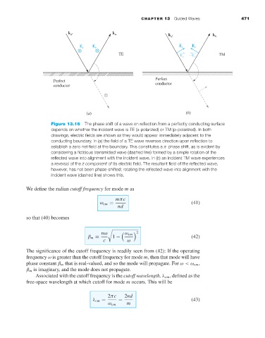
Figure 13.16 The phase shift of a wave on reflection from a perfectly conducting surface
depends on whether the incident wave is TE (s-polarized) or TM (p-polarized). In both
drawings, electric fields are shown as they would appear immediately adjacent to the
conducting boundary. In (a) the field of a TE wave reverses direction upon reflection to
establish a zero net field at the boundary. This constitutes a π phase shift, as is evident by
considering a fictitious transmitted wave (dashed line) formed by a simple rotation of the
reflected wave into alignment with the incident wave. In (b)an incident TM wave experiences
areversal of the z component of its electric field. The resultant field of the reflected wave,
however, has not been phase-shifted; rotating the reflected wave into alignment with the
incident wave (dashed line) shows this.
We define the radian cutoff frequency for mode m as
mπc
ω cm = (41)
nd
so that (40) becomes
nω ω cm 2
β m = 1 − (42)
c ω
The significance of the cutoff frequency is readily seen from (42): If the operating
frequency ω is greater than the cutoff frequency for mode m, then that mode will have
phase constant β m that is real-valued, and so the mode will propagate. For ω< ω cm ,
β m is imaginary, and the mode does not propagate.
Associated with the cutoff frequency is the cutoff wavelength, λ cm , defined as the
free-space wavelength at which cutoff for mode m occurs. This will be
2πc 2nd
λ cm = = (43)
ω cm m