
Page 484 - Engineering Electromagnetics, 8th Edition
P. 484
466 ENGINEERING ELECTROMAGNETICS
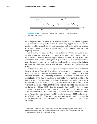
Figure 13.12 Plane wave representation of TE and TM modes in a
parallel-plate guide.
the mode propagates. The TEM mode, however, has no cutoff; it will be supported
at any frequency. At a given frequency, the guide may support several modes, the
quantity of which depends on the plate separation and on the dielectric constant
of the interior medium, as will be shown. The number of modes increases as the
frequency is raised.
So to answer our initial question on the distinction between transmission lines
and waveguides, we can state the following: Transmission lines consist of two or
more conductors and as a rule will support TEM waves (or something which could
approximate such a wave). A waveguide may consist of one or more conductors, or
no conductors at all, and will support waveguide modes of forms similar to those
just described. Waveguides may or may not support TEM waves, depending on the
design.
In the parallel-plate guide, two types of waveguide modes can be supported.
These are shown in Figure 13.12 as arising from the s and p orientations of the plane
wave polarizations. In a manner consistent with our previous discussions on oblique
reflection (Section 12.5), we identify a transverse electric or TE mode when E is
perpendicular to the plane of incidence (s-polarized); this positions E parallel to the
transverse plane of the waveguide, as well as to the boundaries. Similarly, a transverse
magnetic or TM mode results withap polarized wave; the entire H field is in the
y direction and is thus within the transverse plane of the guide. Both possibilities
are illustrated in Figure 13.12. Note, for example, that with E in the y direction
(TE mode), H will have x and z components. Likewise, a TM mode will have
3
x and z components of E. In any event, the reader can verify from the geome-
try of Figure 13.12 that it is not possible to achieve a purely TEM mode for val-
ues of θ other than 90 . Other wave polarizations are possible that lie between the
◦
TE and TM cases, but these can always be expressed as superpositions of TE and
TM modes.
3 Other types of modes can exist in other structures (not the parallel-plate guide) in which both E and
H have z components. These are known as hybrid modes, and they typically occur in guides with
cylindrical cross sections, such as the optical fiber.