
Page 483 - Engineering Electromagnetics, 8th Edition
P. 483
CHAPTER 13 Guided Waves 465
Figure 13.10 Optical fiber waveguide,
with the core dielectric (ρ< a)ofrefractive
index n 1 . The cladding dielectric (a <ρ < b)is
of index n 2 < n 1 .
which, as discussed in Section 13.1, is a transverse electromagnetic, or TEM, wave.
The wavevector k, shown in Figure 13.1, indicates the direction of wave travel as well
as the direction of power flow.
As the frequency is increased, a remarkable change occurs in the way the fields
progagate down the line. Although the original field configuration of Figure 13.1 may
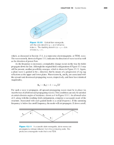
still be present, another possibility emerges, which is shown in Figure 13.11. Again,
a plane wave is guided in the z direction, but by means of a progression of zig-zag
reflections at the upper and lower plates. Wavevectors k u and k d are associated with
the upward-and downward-propagating waves, respectively, and these have identical
magnitudes,
√
|k u |=|k d |= k = ω µ
For such a wave to propagate, all upward-propagating waves must be in phase (as
must be true of all downward-propagating waves). This condition can only be satisfied
at certain discrete angles of incidence, shown as θ in Figure 13.11. An allowed value
of θ, along with the resulting field configuration, comprise a waveguide mode of the
structure. Associated with each guided mode is a cutoff frequency.If the operating
frequency is below the cutoff frequency, the mode will not propagate. If above cutoff,
k u θ k d k u
θ
Figure 13.11 In a parallel-plate waveguide, plane waves can
propagate by oblique reflection from the conducting walls. This
produces a waveguide mode that is not TEM.