Page 476 - Engineering Electromagnetics, 8th Edition
P. 476
458                ENGINEERING ELECTROMAGNETICS

                                                       2
                                                                             2
                                                                                 2
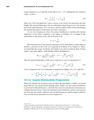
                                     center conductor is πa and that of the outer is π(c −b ). Adding the two resistance
                                     values, we have
                                                                 1     1    1
                                                            R =       2  +  2  2                     (16)
                                                                σ c π  a  c − b
                                     Only one of the four parameter values remains to be found, the inductance per unit
                                     length. The external inductance that we calculated at high frequencies is the greatest
                                     part of the total inductance. To it, however, must be added smaller terms representing
                                     the internal inductances of the inner and outer conductors.
                                        At very low frequencies where the current distribution is uniform, the internal
                                     inductance of the center conductor is the subject of Problem 43 in Chapter 8; the
                                     relationship is also given as Eq. (62) in Section 8.10:
                                                                         µ
                                                                  L a,int =                          (17)
                                                                         8π
                                        The determination of the internal inductance of the outer shell is a more difficult
                                     problem, and most of the work was requested in Problem 36 in Chapter 8. There,
                                     we found that the energy stored per unit length in an outer cylindrical shell of inner
                                     radius b and outer radius c with uniform current distribution is
                                                            µI  2               4c 2   c
                                                                           2
                                                                      2
                                                   W H =             b − 3c +        ln
                                                              2
                                                         16π(c − b )           c − b 2  b
                                                                  2
                                                                                2
                                     Thus the internal inductance of the outer conductor at very low frequencies is
                                                                                   2
                                                              µ       2     2    4c     c
                                                   L bc,int =        b − 3c +         ln             (18)
                                                              2
                                                                                2
                                                          8π(c − b )           c − b 2  b
                                                                  2
                                     At low frequencies the total inductance is obtained by adding (11), (17), and (18):
                                                  µ     b   1      1       2    2    4c 2   c
                                             L =      ln  +  +           b − 3c +         ln         (19)
                                                                  2
                                                                                    2
                                                                      2
                                                 2π     a   4   4(c − b )          c − b 2  b
                                     13.1.3 Coaxial (Intermediate Frequencies)
                                     There still remains the frequency interval where the skin depth is neither very much
                                     larger than nor very much smaller than the radius. In this case, the current distribution
                                     is governed by Bessel functions, and both the resistance and internal inductance are
                                     complicated expressions. Values are tabulated in the handbooks, and it is necessary to
                                     use them for very small conductor sizes at high frequencies and for larger conductor
                                     sizes used in power transmission at low frequencies. 1


                                     1  Bessel functions are discussed within the context of optical fiber in Section 13.7. The current
                                     distribution, internal inductance, and internal resistance of round wires is discussed (with numerical
                                     examples) in Weeks, pp. 35–44. See the References at the end of this chapter.

