
Page 505 - Engineering Electromagnetics, 8th Edition
P. 505
CHAPTER 13 Guided Waves 487
Substituting (104) and (105) into Eqs. (96e), (96c), and (96a) leads to the following
expressions for the TE m0 mode fields:
E ys = E 0 sin (κ m x) e − jβ m0 z (106)
β m0 − jβ m0 z
H xs =− E 0 sin (κ m x) e (107)
ωµ
κ m − jβ m0 z
H zs = j E 0 cos(κ m x)e (108)
ωµ
It can be seen that these expressions are identical to the parallel-plate fields, Eqs. (65),
(71), and (72). For TE m0 ,weagain note that the subscripts indicate that there are m
half cycles of the electric field over the x dimension and there is zero variation in y.
The cutoff frequency for the TE m0 mode is given by (101), appropriately modified:
mπc
ω Cm0 = (109)
na
Using (109) in (99), the phase constant is
nω mπc 2
β m0 = 1 − (110)
c ωna
All of the implications on mode behavior above and below cutoff are exactly the same
as we found for the parallel-plate guide. The plane wave analysis is also carried out in
the same manner. TE m0 modes can be modeled as plane waves that propagate down
the guide by reflecting between the vertical side walls.
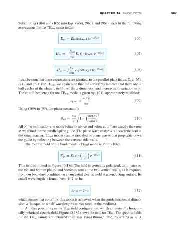
The electric field of the fundamental (TE 10 ) mode is, from (106):
πx
E ys = E 0 sin e − jβ 10 z (111)
a
This field is plotted in Figure 13.18a. The field is vertically polarized, terminates on
the top and bottom plates, and becomes zero at the two vertical walls, as is required
from our boundary condition on a tangential electric field at a conducting surface. Its
cutoff wavelength is found from (102) to be
λ C10 = 2na (112)
which means that cutoff for this mode is achieved when the guide horizontal dimen-
sion, a,is equal to a half-wavelength (as measured in the medium).
Another possibility is the TE 0p field configuration, which consists of a horizon-
tally polarized electric field. Figure 13.18b shows the field for TE 01 . The specific fields
for the TE 0p family are obtained from Eqs. (96a) through (96e) by setting m = 0,