
Page 506 - Engineering Electromagnetics, 8th Edition
P. 506
488 ENGINEERING ELECTROMAGNETICS
(a)
(b)
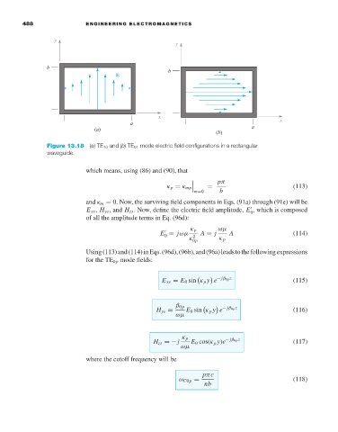
Figure 13.18 (a)TE 10 and (b)TE 01 mode electric field configurations in a rectangular
waveguide.
which means, using (86) and (90), that
pπ
(113)
=
m=0
κ p = κ mp b
and κ m = 0. Now, the surviving field components in Eqs. (91a) through (91e) will be
E xs , H ys , and H zs .Now, define the electric field amplitude, E , which is composed
0
of all the amplitude terms in Eq. (96d):
κ p ωµ
E = jωµ A = j A (114)
0
κ 2 0p κ p
Using(113)and(114)inEqs.(96d),(96b),and(96a)leadstothefollowingexpressions
for the TE 0p mode fields:
E xs = E 0 sin κ p y e − jβ 0p z (115)
β 0p − jβ 0p z
H ys = E 0 sin κ p y e (116)
ωµ
κ p
H zs =− j E 0 cos(κ p y)e − jβ 0p z (117)
ωµ
where the cutoff frequency will be
pπc
ω C0p = (118)
nb