
Page 510 - Engineering Electromagnetics, 8th Edition
P. 510
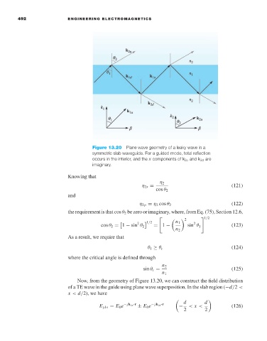
492                ENGINEERING ELECTROMAGNETICS


                                              Figure 13.20 Plane wave geometry of a leaky wave in a
                                              symmetric slab waveguide. For a guided mode, total reflection
                                              occurs in the interior, and the x components of k 2u and k 2d are
                                              imaginary.

                                     Knowing that
                                                                        η 2
                                                                 η 2s =                             (121)
                                                                       cos θ 2
                                     and
                                                                η 2p = η 2 cos θ 2                  (122)
                                     the requirement is that cos θ 2 be zero or imaginary, where, from Eq. (75), Section 12.6,
                                                                                  2
                                                                                          1/2

                                                               2                     2
                                                                    1/2       n 1
                                                  cos θ 2 = 1 − sin θ 2  = 1 −     sin θ 1          (123)
                                                                              n 2
                                     As a result, we require that
                                                                   θ 1 ≥ θ c                        (124)
                                     where the critical angle is defined through
                                                                         n 2
                                                                  sin θ c =                         (125)
                                                                         n 1
                                        Now, from the geometry of Figure 13.20, we can construct the field distribution
                                     of a TE wave in the guide using plane wave superposition. In the slab region (−d/2 <
                                     x < d/2), we have
                                                                                 d       d
                                                 E y1s = E 0 e − jk 1u ·r  ± E 0 e − jk 1d ·r  −  < x <  (126)
                                                                                 2       2