Page 513 - Engineering Electromagnetics, 8th Edition
P. 513
CHAPTER 13 Guided Waves 495
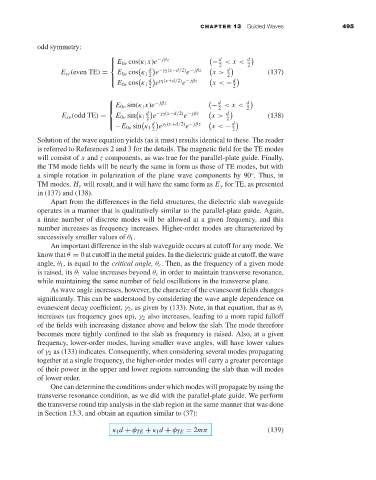
odd symmetry:
d
E 0e cos(κ 1 x)e − jβz − < x < d
2 2
d −γ 2 (x−d/2) − jβz d
E se (even TE) = E 0e cos κ 1 2 e e x > 2 (137)
d d
e
E 0e cos κ 1 x < −
e γ 2 (x+d/2) − jβz
2 2
d d
E 0o sin(κ 1 x)e − jβz − < x <
2 2
d −γ 2 (x−d/2) − jβz d
E so (odd TE) = E 0o sin κ 1 2 e e x > 2 (138)
d γ 2 (x+d/2) − jβz d
e e
−E 0o sin κ 1 2 x < − 2
Solution of the wave equation yields (as it must) results identical to these. The reader
is referred to References 2 and 3 for the details. The magnetic field for the TE modes
will consist of x and z components, as was true for the parallel-plate guide. Finally,
the TM mode fields will be nearly the same in form as those of TE modes, but with
a simple rotation in polarization of the plane wave components by 90 . Thus, in
◦
TM modes, H y will result, and it will have the same form as E y for TE, as presented
in (137) and (138).
Apart from the differences in the field structures, the dielectric slab waveguide
operates in a manner that is qualitatively similar to the parallel-plate guide. Again,
a finite number of discrete modes will be allowed at a given frequency, and this
number increases as frequency increases. Higher-order modes are characterized by
successively smaller values of θ 1 .
An important difference in the slab waveguide occurs at cutoff for any mode. We
know that θ = 0at cutoff in the metal guides. In the dielectric guide at cutoff, the wave
angle, θ 1 ,is equal to the critical angle, θ c . Then, as the frequency of a given mode
is raised, its θ 1 value increases beyond θ c in order to maintain transverse resonance,
while maintaining the same number of field oscillations in the transverse plane.
As wave angle increases, however, the character of the evanescent fields changes
significantly. This can be understood by considering the wave angle dependence on
evanescent decay coefficient, γ 2 ,asgiven by (133). Note, in that equation, that as θ 1
increases (as frequency goes up), γ 2 also increases, leading to a more rapid falloff
of the fields with increasing distance above and below the slab. The mode therefore
becomes more tightly confined to the slab as frequency is raised. Also, at a given
frequency, lower-order modes, having smaller wave angles, will have lower values
of γ 2 as (133) indicates. Consequently, when considering several modes propagating
together at a single frequency, the higher-order modes will carry a greater percentage
of their power in the upper and lower regions surrounding the slab than will modes
of lower order.
One can determine the conditions under which modes will propagate by using the
transverse resonance condition, as we did with the parallel-plate guide. We perform
the transverse round trip analysis in the slab region in the same manner that was done
in Section 13.3, and obtain an equation similar to (37):
κ 1 d + φ TE + κ 1 d + φ TE = 2mπ (139)

