
Page 512 - Engineering Electromagnetics, 8th Edition
P. 512
494 ENGINEERING ELECTROMAGNETICS
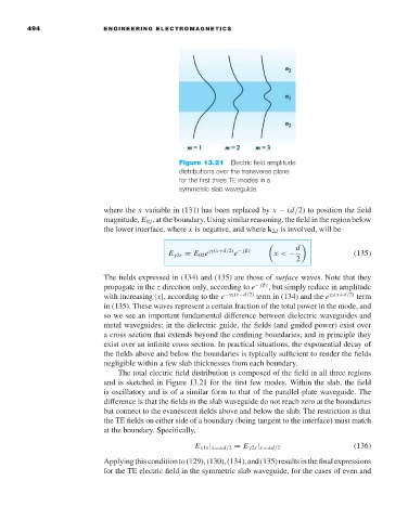
Figure 13.21 Electric field amplitude
distributions over the transverse plane
for the first three TE modes in a
symmetric slab waveguide.
where the x variable in (131) has been replaced by x − (d/2) to position the field
magnitude, E 02 ,at the boundary. Using similar reasoning, the field in the region below
the lower interface, where x is negative, and where k 2d is involved, will be
d
E y2s = E 02 e γ 2 (x+d/2) − jβz x < − (135)
e
2
The fields expressed in (134) and (135) are those of surface waves. Note that they
propagate in the z direction only, according to e − jβz ,but simply reduce in amplitude
with increasing |x|, according to the e −γ 2 (x−d/2) term in (134) and the e γ 2 (x+d/2) term
in (135). These waves represent a certain fraction of the total power in the mode, and
so we see an important fundamental difference between dielectric waveguides and
metal waveguides: in the dielectric guide, the fields (and guided power) exist over
a cross section that extends beyond the confining boundaries, and in principle they
exist over an infinite cross section. In practical situations, the exponential decay of
the fields above and below the boundaries is typically sufficient to render the fields
negligible within a few slab thicknesses from each boundary.
The total electric field distribution is composed of the field in all three regions
and is sketched in Figure 13.21 for the first few modes. Within the slab, the field
is oscillatory and is of a similar form to that of the parallel-plate waveguide. The
difference is that the fields in the slab waveguide do not reach zero at the boundaries
but connect to the evanescent fields above and below the slab. The restriction is that
the TE fields on either side of a boundary (being tangent to the interface) must match
at the boundary. Specifically,
(136)
E y1s | x=±d/2 = E y2s | x=±d/2
Applyingthisconditionto(129),(130),(134),and(135)resultsinthefinalexpressions
for the TE electric field in the symmetric slab waveguide, for the cases of even and