
Page 509 - Engineering Electromagnetics, 8th Edition
P. 509
CHAPTER 13 Guided Waves 491
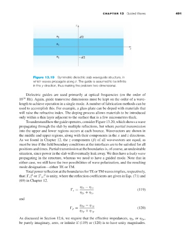
Figure 13.19 Symmetric dielectric slab waveguide structure, in
which waves propagate along z. The guide is assumed to be infinite
in the y direction, thus making the problem two-dimensional.
Dielectric guides are used primarily at optical frequencies (on the order of
10 14 Hz). Again, guide transverse dimensions must be kept on the order of a wave-
length to achieve operation in a single mode. A number of fabrication methods can be
used to accomplish this. For example, a glass plate can be doped with materials that
will raise the refractive index. The doping process allows materials to be introduced
only within a thin layer adjacent to the surface that is a few micrometers thick.
Tounderstandhowtheguideoperates,considerFigure13.20,whichshowsawave
propagating through the slab by multiple reflections, but where partial transmission
into the upper and lower regions occurs at each bounce. Wavevectors are shown in
the middle and upper regions, along with their components in the x and z directions.
As we found in Chapter 12, the z components (β)of all wavevectors are equal, as
must be true if the field boundary conditions at the interfaces are to be satisfied for all
positions and times. Partial transmission at the boundaries is, of course, an undesirable
situation, since power in the slab will eventually leak away. We thus have a leaky wave
propagating in the structure, whereas we need to have a guided mode. Note that in
either case, we still have the two possibilities of wave polarization, and the resulting
mode designation—either TE or TM.
Total power reflection at the boundaries for TE or TM waves implies, respectively,
2
2
that | s | or | p | is unity, where the reflection coefficients are given in Eqs. (71) and
(69) in Chapter 12.
η 2s − η 1s
s = (119)
η 2s + η 1s
and
η 2p − η 1p
p = (120)
η 2p + η 1p
As discussed in Section 12.6, we require that the effective impedances, η 2s or η 2p ,
be purely imaginary, zero, or infinite if (119) or (120) is to have unity magnitudes.