
Page 524 - Engineering Electromagnetics, 8th Edition
P. 524
506 ENGINEERING ELECTROMAGNETICS
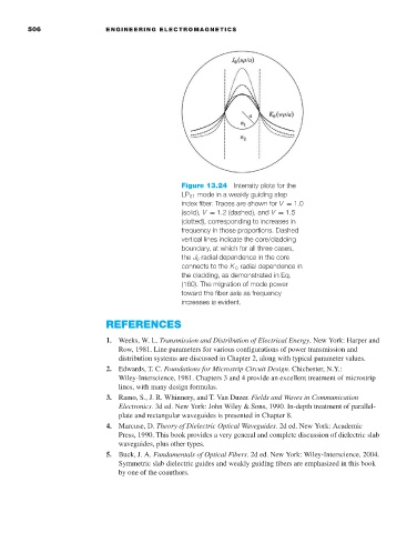
Figure 13.24 Intensity plots for the
LP 01 mode in a weakly guiding step
index fiber. Traces are shown for V = 1.0
(solid), V = 1.2 (dashed), and V = 1.5
(dotted), corresponding to increases in
frequency in those proportions. Dashed
vertical lines indicate the core/cladding
boundary, at which for all three cases,
the J 0 radial dependence in the core
connects to the K 0 radial dependence in
the cladding, as demonstrated in Eq.
(160). The migration of mode power
toward the fiber axis as frequency
increases is evident.
REFERENCES
1. Weeks, W. L. Transmission and Distribution of Electrical Energy.New York: Harper and
Row, 1981. Line parameters for various configurations of power transmission and
distribution systems are discussed in Chapter 2, along with typical parameter values.
2. Edwards, T. C. Foundations for Microstrip Circuit Design. Chichester, N.Y.:
Wiley-Interscience, 1981. Chapters 3 and 4 provide an excellent treatment of microstrip
lines, with many design formulas.
3. Ramo, S., J. R. Whinnery, and T. Van Duzer. Fields and Waves in Communication
Electronics.3d ed. New York: John Wiley & Sons, 1990. In-depth treatment of parallel-
plate and rectangular waveguides is presented in Chapter 8.
4. Marcuse, D. Theory of Dielectric Optical Waveguides.2d ed. New York: Academic
Press, 1990. This book provides a very general and complete discussion of dielectric slab
waveguides, plus other types.
5. Buck, J. A. Fundamentals of Optical Fibers.2d ed. New York: Wiley-Interscience, 2004.
Symmetric slab dielectric guides and weakly guiding fibers are emphasized in this book
by one of the coauthors.