Page 563 - Engineering Electromagnetics, 8th Edition
P. 563
CHAPTER 14  ELECTROMAGNETIC RADIATION AND ANTENNAS              545

                     by radial distance, r, and with relative orientations that are specified by values of θ,as
                                                       5
                     measured with respect to each antenna axis. With antenna 1 serving as the transmitter
                     and antenna 2 serving as the receiver, the radiation pattern of antenna 1 is given as
                     a function of θ 1 and φ 1 , while the receiving pattern of antenna 2 (equivalent to its
                     radiation pattern) is given as a function of θ 2 and φ 2 .
                         A convenient way to express the received power in an antenna is through its
                                                                2
                     effective area, denoted A e (θ, φ), and expressed in m . Refer to Figure 14.18, and
                     consider the average power density at the receiver (antenna 2) position, originating
                     from the transmitter (antenna 1). As per Eqs. (25) and (26), this will be the magnitude
                                                                    2
                     of the Poynting vector at that location, S r (r,θ 1 ,φ 1 )inW/m , where a dependence on
                     φ is now necessary to describe all possible relative orientations. The effective area
                     of the receiving antenna is defined such that when the power density is multiplied by
                     the effective area, the power dissipated by a matched load at the receiving antenna is
                     obtained. With antenna 2 as the receiver, we write

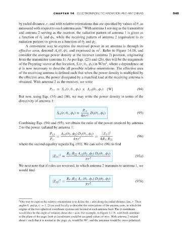
                                      P L2 = S r1 (r,θ 1 ,φ 1 ) × A e2 (θ 2 ,φ 2 )  [W]  (94)
                     But now, using Eqs. (34) and (38), we may write the power density in terms of the
                     directivity of antenna 1:

                                                       P r1
                                         S r1 (r,θ 1 ,φ 1 ) =  D 1 (θ 1 ,φ 1 )       (95)
                                                      4πr 2
                     Combining Eqs. (94) and (95), we obtain the ratio of the power received by antenna
                     2to the power radiated by antenna 1:
                                      P L2  A e2 (θ 2 ,φ 2 ) D 1 (θ 1 ,φ 1 )  |Z 21 | 2
                                         =                    =                      (96)
                                      P r1        4πr 2          4R 11 R 22
                     where the second equality repeats Eq. (93). We can solve (96) to find

                                               R 11 R 22 A e2 (θ 2 ,φ 2 ) D 1 (θ 1 ,φ 1 )
                                           2                                        (97a)
                                       |Z 21 | =
                                                         πr 2
                     We next note that if roles are reversed, in which antenna 2 transmits to antenna 1, we
                     would find

                                               R 11 R 22 A e1 (θ 1 ,φ 1 ) D 2 (θ 2 ,φ 2 )
                                           2                                        (97b)
                                       |Z 12 | =
                                                         πr 2


                     5 One way to express the relative orientations is to define the z axis along the radial distance line, r. Then
                     angles θ i and φ i (i = 1, 2) are used locally to describe the orientations of the antenna axes, in which the
                     origins of the two spherical coordinate systems are located at each antenna feed. The φ coordinate
                     would thus be the angle of rotation about the r axis. For example, in Figure 14.18, with both antennas
                     in the plane of the page, both φ coordinates could be assigned values of zero. With antenna 2 rotated
                     about r such that it is normal to the page, φ 2 would be 90 , and the antennas would be cross-polarized.
                                                          ◦

