
Page 559 - Engineering Electromagnetics, 8th Edition
P. 559
CHAPTER 14 ELECTROMAGNETIC RADIATION AND ANTENNAS 541
D14.8. In an endfire linear dipole array in which ξ =−kd, what minimum
element spacing d in wavelengths results in bi-directional operation, in which
equal intensities occur in the H plane at φ = 0 and φ = π?
Ans. d = λ/2
D14.9. Fora linear dipole array in which the element spacing is d = λ/4,
what current phase ξ will result in a main beam in the direction of a) φ = 30 ;
◦
b) φ = 45 .
◦
√ √
Ans. −π 3/4; −π 2/4
14.7 ANTENNAS AS RECEIVERS
We next turn to the other fundamental purpose of an antenna, which is its use as
a means to detect, or receive, radiation that originates from a distant source. We
will approach this problem through study of a transmit-receive antenna system. This
is composed of two antennas, along with their supporting electronics, that play the
interchangeable roles of transmitter and detector.
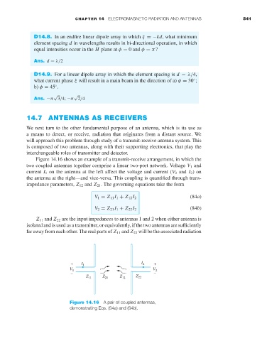
Figure 14.16 shows an example of a transmit-receive arrangement, in which the
two coupled antennas together comprise a linear two-port network. Voltage V 1 and
current I 1 on the antenna at the left affect the voltage and current (V 2 and I 2 )on
the antenna at the right—and vice-versa. This coupling is quantified through trans-
impedance parameters, Z 12 and Z 21 . The governing equations take the form
V 1 = Z 11 I 1 + Z 12 I 2 (84a)
V 2 = Z 21 I 1 + Z 22 I 2 (84b)
Z 11 and Z 22 are the input impedances to antennas 1 and 2 when either antenna is
isolated and is used as a transmitter, or equivalently, if the two antennas are sufficiently
faraway from each other. The real parts of Z 11 and Z 22 will be the associated radiation
+ I 1 I 2 +
V 1 V 2
– –
Z 11 Z 21 Z 12 Z 22
Figure 14.16 A pair of coupled antennas,
demonstrating Eqs. (84a) and (84b).