
Page 556 - Engineering Electromagnetics, 8th Edition
P. 556
538 ENGINEERING ELECTROMAGNETICS
P(r,f)
r f
I 0 I e jx I e j2x I e j3x I e j4x ... I e j(n–1)x
0
0
0
0
0
x
d
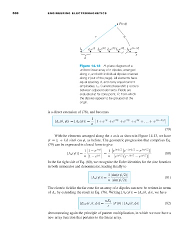
Figure 14.13 H-plane diagram of a
uniform linear array of n dipoles, arranged
along x, and with individual dipoles oriented
along z (out of the page). All elements have
equal spacing, d, and carry equal current
amplitudes, I 0 . Current phase shift ξ occurs
between adjacent elements. Fields are
evaluated at far-zone point, P,from which
the dipoles appear to be grouped at the
origin.
is a direct extension of (78), and becomes
1 jψ j2ψ j3ψ 4ψ
|A n (θ, φ)| = |A n (ψ)| = 1 + e + e + e + e + ... + e j(n−1)ψ
n
(79)
With the elements arranged along the x axis as shown in Figure 14.13, we have
ψ = ξ + kd sin θ cos φ,as before. The geometric progression that comprises Eq.
(79) can be expressed in closed form to give
jnψ/2
1 1 − e jnψ 1 e e − jnψ/2 − e jnψ/2
|A n (ψ)| = = (80)
e
1 − e n jψ/2 e − jψ/2 − e
n jψ jψ/2
In the far right side of Eq. (80), we recognize the Euler identities for the sine function
in both numerator and denominator, leading finally to
1 |sin(nψ/2)|
|A n (ψ)| = (81)
n |sin(ψ/2)|
The electric field in the far zone for an array of n dipoles can now be written in terms
of A n by extending the result in Eq. (76). Writing |A n (ψ)| = |A n (θ, φ)|,wehave
nE 0
|E θ P (r,θ,φ)|= |F(θ) ||A n (θ, φ)| (82)
r
demonstrating again the principle of pattern multiplication, in which we now have a
new array function that pertains to the linear array.