Page 553 - Engineering Electromagnetics, 8th Edition
P. 553
CHAPTER 14  ELECTROMAGNETIC RADIATION AND ANTENNAS              535

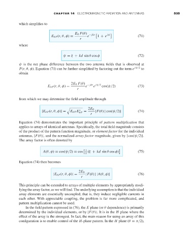
                     which simplifies to

                                                   E 0 F(θ)
                                      E θ P (r,θ,φ) =     e − jkr  1 + e jψ          (71)
                                                      r
                     where


                                             ψ = ξ + kd sin θ cos φ                  (72)
                     ψ is the net phase difference between the two antenna fields that is observed at
                     P(r,θ,φ). Equation (71) can be further simplified by factoring out the term e  jψ/2  to
                     obtain


                                                 2E 0 F(θ)
                                                             e
                                    E θ P (r,θ,φ) =      e − jkr jψ/2  cos(ψ/2)      (73)
                                                    r
                     from which we may determine the field amplitude through


                                                          2E 0
                                                     ∗
                                 |E θ P (r,θ,φ)|=  E θ P E θ P  =  |F(θ)|| cos(ψ/2)|  (74)
                                                           r
                     Equation (74) demonstrates the important principle of pattern multiplication that
                     applies to arrays of identical antennas. Specifically, the total field magnitude consists
                     of the product of the pattern function magnitude, or element factor for the individual
                     antennas, |F(θ)|, and the normalized array factor magnitude, given by | cos(ψ/2)|.
                     The array factor is often denoted by


                                  A(θ, φ) = cos(ψ/2) = cos    1  (ξ + kd sin θ cos φ)    (75)
                                                         2
                     Equation (74) then becomes


                                                     2E 0
                                       |E θ P (r,θ,φ)|=  |F(θ) ||A(θ, φ)|            (76)
                                                      r
                     This principle can be extended to arrays of multiple elements by appropriately modi-
                     fying the array factor, as we will find. The underlying assumption is that the individual
                     array elements are essentially uncoupled; that is, they induce negligible currents in
                     each other. With appreciable coupling, the problem is far more complicated, and
                     pattern multiplication cannot be used.
                         In the field pattern expressed in (76), the E plane (or θ dependence) is primarily
                     determined by the individual elements, or by |F(θ)|.Itisinthe H plane where the
                     effect of the array is the strongest. In fact, the main reason for using an array of this
                     configuration is to enable control of the H-plane pattern. In the H plane (θ = π/2),

