
Page 550 - Engineering Electromagnetics, 8th Edition
P. 550
532 ENGINEERING ELECTROMAGNETICS
2.5 250
2.0 200
1.5 150
D R rad [Ω]
1.0 100
0.5 50
.25 .50 .75 1.0
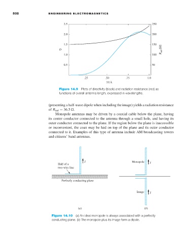
Figure 14.9 Plots of directivity (black) and radiation resistance (red) as
functions of overall antenna length, expressed in wavelengths.
(presenting a half-wave dipole when including the image) yields a radiation resistance
of R rad = 36.5
.
Monopole antennas may be driven by a coaxial cable below the plane, having
its center conductor connected to the antenna through a small hole, and having its
outer conductor connected to the plane. If the region below the plane is inaccessible
or inconvenient, the coax may be laid on top of the plane and its outer conductor
connected to it. Examples of this type of antenna include AM broadcasting towers
and citizens’ band antennas.
I Monopole
Half of a I
two-wire line
Perfectly conducting plane
Image I
(a) (b)
Figure 14.10 (a)An ideal monopole is always associated with a perfectly
conducting plane. (b) The monopole plus its image form a dipole.