
Page 547 - Engineering Electromagnetics, 8th Edition
P. 547
CHAPTER 14 ELECTROMAGNETIC RADIATION AND ANTENNAS 529
57.5˚
(a) (b)
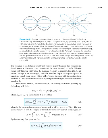
Figure 14.8 E-plane plots, normalized to maxima of 1.0, found from F (θ) for dipole
antennas having overall lengths, 2 ,of(a) λ/16 (solid black), λ/2 (dashed), and λ (red), and (b)
1.3λ (dashed), and 2λ (red). In (a), the beam-narrowing trend is evident as length increases (or
as wavelength decreases). Note that the λ/16 curves are nearly circular and thus approximate
the Hertzian dipole pattern. At lengths that exceed one wavelength, sidelobes begin to develop,
as exhibited in the smaller beams in the 1.3λ pattern in (b). As length increases, the sidelobes
grow to form the four symmetrically arranged main lobes of the 2λ antenna, where the lobe in
◦
the first quadrant maximizes at θ = 57.5 . The main lobes along x that were present in the 1.3λ
antenna diminish with increasing length, and have vanished completely when the length
reaches 2λ.
The presence of sidelobes is usually not wanted, mainly because they represent ra-
diated power in directions other than that of the main beam (θ = π/2). Sidelobe
power will therefore likely miss the intended receiver. In addition, the sidelobe di-
rections change with wavelength, and will therefore impart an angular spread to
a radiated signal, to an extent which will of course increase with increasing signal
bandwidth. These problems are avoided by using antenna lengths that are less than one
wavelength.
The radiation intensity can now be found for the dipole antenna by using Eq.
(34), along with (25):
1
2 Re E θs H ∗ r 2
K(θ) = r S r = φs
2
where H φs = E θs /η. Substituting (57), we obtain
ηI 2 15 I 2
2
K(θ) = 0 [F(θ)] = 0 [F(θ)] 2 W/Sr (60)
8π 2 π
where in the last equality free space is assumed, in which η = η 0 = 120π. The total
radiated power is now the integral of the radiation intensity over all solid angles, or
4π 2π π
P r = Kd
= K(θ) sin θ dθ dφ (61)
0 0 0
Again assuming free space we find
π
2
P r = 30 I 0 2 [F(θ)] sin θ dθ W (62)
0