Page 546 - Engineering Electromagnetics, 8th Edition
P. 546

528                ENGINEERING ELECTROMAGNETICS

                                     integral as A,we write:

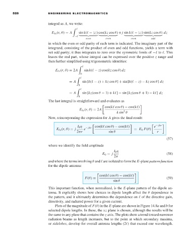
                                       E θs (r,θ) = A  sin k(  −|z|) cos(kz cos θ) + j sin k(  −|z|) sin(kz cos θ) dz
                                                   −
                                                         even       even         even       odd
                                     in which the even or odd parity of each term is indicated. The imaginary part of the
                                     integrand, consisting of the product of even and odd functions, yields a term with
                                     net odd parity; it thus integrates to zero over the symmetric limits of −  to  . This
                                     leaves the real part, whose integral can be expressed over the positive z range and
                                     then further simplified using trigonometric identities:

                                         E θs (r,θ) = 2A  sin k(  − z) cos(kz cos θ) dz
                                                      0

                                                = A    sin [k(  − z) + kz cos θ] + sin [k(  − z) − kz cos θ] dz
                                                     0

                                                = A    sin [kz(cos θ − 1) + k ] − sin [kz(cos θ + 1) − k ] dz
                                                     0
                                     The last integral is straightforward and evaluates as
                                                                   cos(k  cos θ) − cos(k )

                                                      E θs (r,θ) = 2A
                                                                             2
                                                                          k sin θ
                                     Now, reincorporating the expression for A gives the final result:
                                                     I 0 η      cos(k  cos θ) − cos(k )        e − jkr
                                         E θs (r,θ) = j  e − jkr                   = E 0 F(θ)
                                                    2πr              sin θ                     r
                                                                                                     (57)
                                     where we identify the field amplitude
                                                                        I 0 η
                                                                  E 0 = j                            (58)
                                                                        2π
                                     and where the terms involving θ and   are isolated to form the E-plane pattern function
                                     for the dipole antenna:

                                                                cos(k  cos θ) − cos(k )

                                                         F(θ) =                                      (59)
                                                                        sin θ
                                     This important function, when normalized, is the E-plane pattern of the dipole an-
                                     tenna. It explicitly shows how choices in dipole length affect the θ dependence in
                                     the pattern, and it ultimately determines the dependence on   of the directive gain,
                                     directivity, and radiated power for a given current.
                                        Plots of the magnitude of F(θ)in the E-plane are shown in Figure 14.8a and b for
                                     selected dipole lengths. In these, the xz plane is chosen, although the results will be
                                     the same in any plane that contains the z axis. The plots show a trend toward narrower
                                     radiation beams as length increases, but to the point at which secondary maxima,
                                     or sidelobes,develop for overall antenna lengths (2 ) that exceed one wavelength.
   541   542   543   544   545   546   547   548   549   550   551