
Page 541 - Engineering Electromagnetics, 8th Edition
P. 541
CHAPTER 14 ELECTROMAGNETIC RADIATION AND ANTENNAS 523
14.3 MAGNETIC DIPOLE
An interesting device that is closely related to the Hertzian dipole is the magnetic
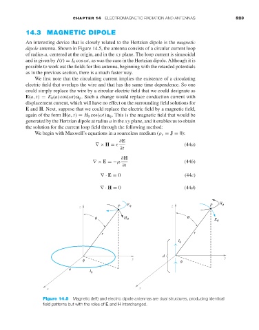
dipole antenna. Shown in Figure 14.5, the antenna consists of a circular current loop
of radius a, centered at the origin, and in the xy plane. The loop current is sinusoidal
and is given by I(t) = I 0 cos ωt,aswas the case in the Hertzian dipole. Although it is
possible to work out the fields for this antenna, beginning with the retarded potentials
as in the previous section, there is a much faster way.
We first note that the circulating current implies the existence of a circulating
electric field that overlaps the wire and that has the same time dependence. So one
could simply replace the wire by a circular electric field that we could designate as
E(a, t) = E 0 (a) cos(ωt) a φ . Such a change would replace conduction current with
displacement current, which will have no effect on the surrounding field solutions for
E and H.Next, suppose that we could replace the electric field by a magnetic field,
again of the form H(a, t) = H 0 cos(ωt) a φ . This is the magnetic field that would be
generated by the Hertzian dipole at radius a in the xy plane, and it enables us to obtain
the solution for the current loop field through the following method:
We begin with Maxwell’s equations in a sourceless medium (ρ v = J = 0):
∂E
∇× H = (44a)
∂t
∂H
∇× E =−µ (44b)
∂t
∇· E = 0 (44c)
∇· H = 0 (44d)
z P E f z P H f
q H q q E q
r r
I 0
d y
f y f
a I 0
x x
Figure 14.5 Magnetic (left) and electric dipole antennas are dual structures, producing identical
field patterns but with the roles of E and H interchanged.