
Page 543 - Engineering Electromagnetics, 8th Edition
P. 543
CHAPTER 14 ELECTROMAGNETIC RADIATION AND ANTENNAS 525
14.4 THIN WIRE ANTENNAS
In addition to giving insights on radiation fundamentals, the Hertzian dipole results
provide us with a basis from which the fields associated with more complicated
antennas can be derived. In this section this methodology is applied to the more
practical problem of straight thin wire antennas of any length. We will find that for
agiven wavelength, changes in antenna length lead to dramatic variations in (and
control of) the radiation pattern. We will also note improvement in directivity and
efficiency when using certain antenna lengths.
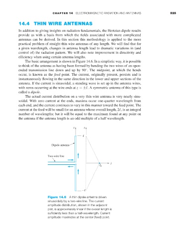
The basic arrangement is shown in Figure 14.6. In a simplistic way, it is possible
to think of the antenna as having been formed by bending the two wires of an open-
ended transmission line down and up by 90 . The midpoint, at which the bends
◦
occur, is known as the feed point. The current, originally present, persists and is
instantaneously flowing in the same direction in the lower and upper sections of the
antenna. If the current is sinusoidal, a standing wave is set up in the antenna wires,
with zeros occurring at the wire ends at z =± .A symmetric antenna of this type is
called a dipole.
The actual current distribution on a very thin wire antenna is very nearly sinu-
soidal. With zero current at the ends, maxima occur one-quarter wavelength from
each end, and the current continues to vary in this manner toward the feed point. The
current at the feed will be small for an antenna whose overall length, 2 ,isan integral
number of wavelengths; but it will be equal to the maximum found at any point on
the antenna if the antenna length is an odd multiple of a half wavelength.
Figure 14.6 A thin dipole antenna driven
sinusoidally by a two-wire line. The current
amplitude distribution, shown in the adjacent
plot, is approximately linear if the overall length is
sufficiently less than a half-wavelength. Current
amplitude maximizes at the center (feed) point.