
Page 551 - Engineering Electromagnetics, 8th Edition
P. 551
CHAPTER 14 ELECTROMAGNETIC RADIATION AND ANTENNAS 533
D14.5. The monopole antenna of Figure 14.10a has a length d/2 = 0.080 m
and may be assumed to carry a triangular current distribution for which the
feed current I 0 is 16.0 A at a frequency of 375 MHz in free space. At point P
(r = 400 m, θ = 60 , φ = 45 ) find (a) H φs ,(b) E θs , and (c) the amplitude of
◦
◦
P r .
Ans. j1.7 mA/m; j0.65 V/m; 1.1 mW/m 2
14.5 ARRAYS OF TWO ELEMENTS
We next address the problem of establishing better control of the directional prop-
erties of antenna radiation. Although some control of directivity is achieved through
adjustment of the length of a wire antenna, these results only appear as changes in
the E-plane pattern. The H-plane pattern always remains a circle (no φ variation), as
long as a single vertical wire antenna is used. By using multiple elements in an array,
significant improvement in directivity as determined in both E and H planes can be
achieved. Our objective in this section is to lay the groundwork for the analysis of
arrays by considering the simple case of using two elements. The resulting methods
are readily extendable to multiple element configurations.
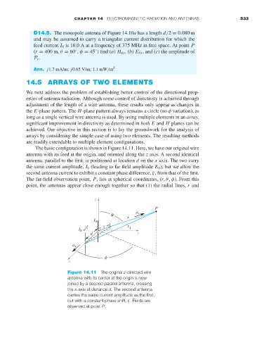
The basic configuration is shown in Figure 14.11. Here, we have our original wire
antenna with its feed at the origin, and oriented along the z axis. A second identical
antenna, parallel to the first, is positioned at location d on the x axis. The two carry
the same current amplitude, I 0 (leading to far-field amplitude E 0 ), but we allow the
second antenna current to exhibit a constant phase difference, ξ, from that of the first.
The far-field observation point, P, lies at spherical coordinates, (r,θ,φ). From this
point, the antennas appear close enough together so that (1) the radial lines, r and
P
a
q r
I 0 r
jx s r 1
I e
0
d
a x
f
x
Figure 14.11 The original z-directed wire
antenna with its center at the origin is now
joined by a second parallel antenna, crossing
the x axis at distance d. The second antenna
carries the same current amplitude as the first,
but with a constant phase shift, ξ. Fields are
observed at point P.