
Page 557 - Engineering Electromagnetics, 8th Edition
P. 557
CHAPTER 14 ELECTROMAGNETIC RADIATION AND ANTENNAS 539
1 1
A 0.5 A 0.5
4
8
–2π –π 0 π 2π –2π –π 0 π 2π
y y
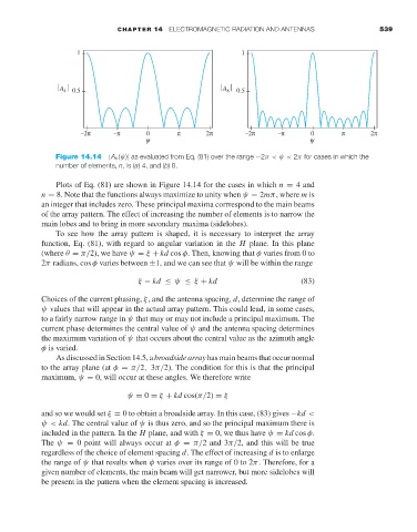
Figure 14.14 |A n (ψ)| as evaluated from Eq. (81) over the range −2π< ψ < 2π for cases in which the
number of elements, n,is(a)4, and (b)8.
Plots of Eq. (81) are shown in Figure 14.14 for the cases in which n = 4 and
n = 8. Note that the functions always maximize to unity when ψ = 2mπ, where m is
an integer that includes zero. These principal maxima corrrespond to the main beams
of the array pattern. The effect of increasing the number of elements is to narrow the
main lobes and to bring in more secondary maxima (sidelobes).
To see how the array pattern is shaped, it is necessary to interpret the array
function, Eq. (81), with regard to angular variation in the H plane. In this plane
(where θ = π/2), we have ψ = ξ + kd cos φ. Then, knowing that φ varies from 0 to
2π radians, cos φ varies between ±1, and we can see that ψ will be within the range
ξ − kd ≤ ψ ≤ ξ + kd (83)
Choices of the current phasing, ξ, and the antenna spacing, d, determine the range of
ψ values that will appear in the actual array pattern. This could lead, in some cases,
to a fairly narrow range in ψ that may or may not include a principal maximum. The
current phase determines the central value of ψ and the antenna spacing determines
the maximum variation of ψ that occurs about the central value as the azimuth angle
φ is varied.
As discussed in Section 14.5, a broadside array has main beams that occur normal
to the array plane (at φ = π/2, 3π/2). The condition for this is that the principal
maximum, ψ = 0, will occur at these angles. We therefore write
ψ = 0 = ξ + kd cos(π/2) = ξ
and so we would set ξ = 0to obtain a broadside array. In this case, (83) gives −kd <
ψ< kd. The central value of ψ is thus zero, and so the principal maximum there is
included in the pattern. In the H plane, and with ξ = 0, we thus have ψ = kd cos φ.
The ψ = 0 point will always occur at φ = π/2 and 3π/2, and this will be true
regardless of the choice of element spacing d. The effect of increasing d is to enlarge
the range of ψ that results when φ varies over its range of 0 to 2π. Therefore, for a
given number of elements, the main beam will get narrower, but more sidelobes will
be present in the pattern when the element spacing is increased.