
Page 562 - Engineering Electromagnetics, 8th Edition
P. 562
544 ENGINEERING ELECTROMAGNETICS
substitution in (90), and using the fact that Z 22 + Z 22 = 2R 22 gives
∗
2
1 Z 21 2 |I 1 | |Z 21 | 2
P L = |I 1 | 2 Re {Z 22 } = (91)
2 2R 22 8R 22
The time-average power transmitted by antenna 1 is
1 1
P r = Re V 1 I ∗ = R 11 |I 1 | 2 (92)
2 1 2
By comparing the above result with Eq. (65), R 11 is interpreted as the radiation
resistance of the transmitting antenna if (1) there are no resistive losses, and (2) the
current amplitude at the driving point is the maximum amplitude, I 0 .Aswe found
earlier, the latter will occur in a dipole if the overall antenna length is an integer
multiple of a half-wavelength. Using (91) and (92), we write the ratio of the received
and transmitted powers:
2
P L |Z 21 |
= (93)
P r 4R 11 R 22
At this stage, more understanding is needed of the transimpedance, Z 21 (or Z 12 ).
This quantity will depend on the distance and relative orientations of the two antennas,
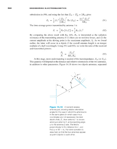
in addition to other parameters. Figure 14.18 shows two dipole antennas, separated
a
E i
q 2
q 1
r
Figure 14.18 A transmit-receive
antenna pair, showing relative orientation
angles for the case in which the antennas lie
in the same plane (in which case the φ
coordinates are not necessary). Incident
electric field, E i ,from antenna 1 is shown
arriving at antenna 2, and presenting angle
α to the antenna 2 axis. The field is
perpendicular to the distance line r , and
thus α = 90 − θ 2 . Far-zone operation is
◦
assumed, so that the two antennas appear
as point objects to each other.