
Page 159 - Subyek Computer Aided Design - [David Planchard] Engineering Design with SOLIDWORKS
P. 159
Engineering Design with SOLIDWORKS® 2018 Fundamentals of Part Modeling
Sketch Entities and Sketch Tools / Linc
D Como,r RectanglP. I Fillet ..
t::J Center Recwngle ) (hamf Pr ...
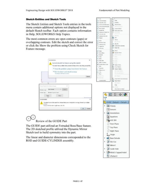
The Sketch Entities and Sketch Tools entries in the tools <:> 3 Point Comer Rectangle lE. Offset Entities ...
menu contain additional options not displayed in the (z> 3 Point Cenler R,,ctangle . ,.._
D l'arallclogram (El Convert ~ntities
default Sketch toolbar. Each option contains information G Straight Slot '@- lntcrsl'rtion ( urvl'
G Cenierpoint Slraight Slot
in Help, SOLIDWORKS Help Topics. (fl> 3 Point Arc SIOt
(;}. Cenlerpoinl Ar<. Slul
The most common errors are open contours (gaps) or 0 l'olygon ~ Trim
Q Circle
overlapping contours. Edit the sketch and correct the error Q Perin>eler Cirde ~ II "
.Il. Jog Line
~ <.:enlerpoinl Arc
or click the Show the problem using Check Sketch for I;! I Construction Geometry
~ Tangent Arc
Feature message. (\ 1 Poini Arr O Makc Palh
Q t lhpse (},~ M irror
{:; Parti.ll C!lipsc * Dynamic Mirror
V Parabola
{'\ Conic
r
N Sµline
SOLIDWORKS x /y Style ~pline ,. 1~
I Cannot rebuild the feature using this sketch (§} Sptine on Surface
• ~ rrruatim l)rlVP.n Cum.
0 Rcplac c Enlity._ .
The sketch has a problem that prevents its feature from rebuilding successfully.
• Point c,i:, l- p
c,i:, inear anern.-
'
~/ Centerline
~ Show the problem using Check Sketch for Feature ei:<1 Circular Pattern. ..
"' Midpoint Line
r ~ rr
~ Exit the sketch and rebuild anyway A 1cx1._
The feature will have an error. Plane
Cancel ' Jt l
-
L Create Sketch from Selections
Customi7P MPnU
~ Repair Sketch
Align
Check Sketch For Feature Usage x
Close Sketch to Model
Base Extrude v Ke t
Feature usage :
Contour type : Multiple Disjoint Closed
Ch~k Close
~
SOLIDWORKS x
I The sketch cannot be used for a feature because an endpoint is wrongly shared by multiple ~ GUIDE (Default<<Default> _[
• entities.
To try to fix the sketch right now, click OK.
~ R!} I History
I OK I Cancel
liflJ Sensors
~ [A] Annotations
~ Equations
o-
Review of the GUIDE Part ~:O AISI 304
dJ Front Plane
The GUIDE part utilized an Extruded Boss/Base feature.
dJ Top Plane
The 2D sketched profile utilized the Dynamic Mirror
dJ Right Plane
Sketch tool to build symmetry into the part.
l. Origin
The linear and diameter dimensions corresponded to the
~ ~ Base Extrude
ROD and GUIDE-CYLINDER assembly.
~ ~ Slot Cut
C3jiiJ Mirror1
~ ~ Guide Hole
~ ~ M3x0.5 Tapped Hole1
g g LPattern1
PAGE2 - 87