Page 160 - Subyek Computer Aided Design - [David Planchard] Engineering Design with SOLIDWORKS
P. 160

Fundamentals of Part Modeling                                                                                                                                 Engineering Design with SOLIDWORKS 2018


                                                The Extruded Cut feature created the Slot-Cut. The Mirror feature created a second Slot-


                                                Cut symmetric about the Right Plane. The Guide Hole utilized the Extruded Cut feature


                                                with the Through All End Condition.


                                                The Hole Wizard created the M3 x0.5 Tapped Hole, the seed feature in the Linear


                                                Pattern. The Linear Pattern feature created multiple instances of the M3 x0.5 Tapped


                                                Hole.


                                                You reused geometry to save design time and rebuild time. The Mirror feature, Linear


                                                Pattern feature, Geometry Pattern option and Sketch Mirror are time saving tools. You


                                                defined materials in the part used by other software applications.


                                                Project Summary


                                                You created three file folders to manage your project models, document templates and


                                                vendor components. The PART-ANSI-MM Part Template was developed and utilized for


                                                three parts: ROD, GUIDE and PLATE.


                                                The PLATE part consisted of an Extruded Boss/Base, Extruded Cut, Fillet and Hole


                                                Wizard features. The ROD consisted of an Extruded Boss/Base, Extruded Cut, Chamfer,


                                                and Hole Wizard features. The ROD illustrated the process to manipulate design changes


                                                with the Rollback bar, Edit Sketch and Edit Feature/Edit Sketch commands. The GUIDE


                                                part utilized an Extruded Boss/Base feature sketch with the Dynamic Mirror Entities tool.


                                                The GUIDE also utilized the Extruded Cut, Mirror, Hole Wizard and Linear Pattern


                                                features.


                                                All sketches for the Extruded Boss/Base and Extruded Cut features utilized geometric


                                                relationships. Incorporate geometric relations such as Horizontal, Vertical, Symmetric,


                                                Equal, Collinear and Coradial into your sketches.


                                                In Project 3, insert the ROD, GUIDE and PLATE parts into a new assembly. In Project 4,


                                                create an assembly drawing and a detailed drawing of the GUIDE part.


                                                Are you ready to start Project 3? Stop! Examine and create additional parts. Perform


                                                design changes. Take chances, make mistakes and have fun with the various features and


                                                commands in the project exercises.


                                                   , ,/


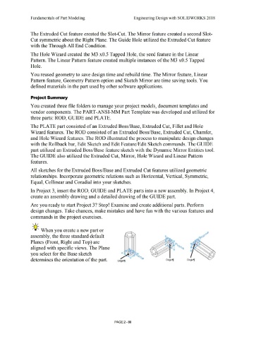
                                                  -;Q~ When you create a new part or


                                                assembly, the three standard default


                                                Planes (Front, Right and Top) are


                                                aligned with specific views. The Plane


                                                you select for the Base sketch


                                                determines the orientation of the part.                                                                                              ongin1l                                                                   Origin11                        Origin1]


                                                                                                                                                                                PAGE2 - 88
   155   156   157   158   159   160   161   162   163   164   165