
Page 163 - Subyek Computer Aided Design - [David Planchard] Engineering Design with SOLIDWORKS
P. 163
Engineering Design with SOLIDWORKS® 201 8 Fundamentals of Part Modeling
25. Describe the procedure to set the Overall drafting standard, units and precision for a
Part document.
26. Describe the procedure to sketch an Elliptical profile.
27. Identify the name of the following feature tool icons.
~ ~g 9 I&] ~ [?s]
A B c D E F
A B c D
E F
28. Identify the name of the following Sketch tool icons.
/ (ii a 0
A B c D E F G H I J
A B c D
E F G H
I J
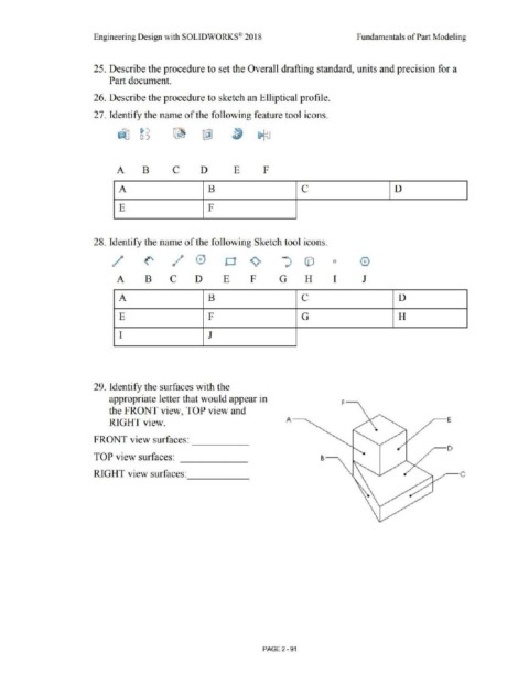
29. Identify the surfaces with the
appropriate letter that would appear in F-
the FRONT view, TOP view and
A---. ;--E
RIGHT view.
FRONT view surfaces:
-----
~ D
TOP view surfaces:
------
RIGHT view surfaces:
PAGE 2 - 91