
Page 168 - Subyek Computer Aided Design - [David Planchard] Engineering Design with SOLIDWORKS
P. 168
Fundamentals of Part Modeling Engineering Design with SOLIDWORKS 2018
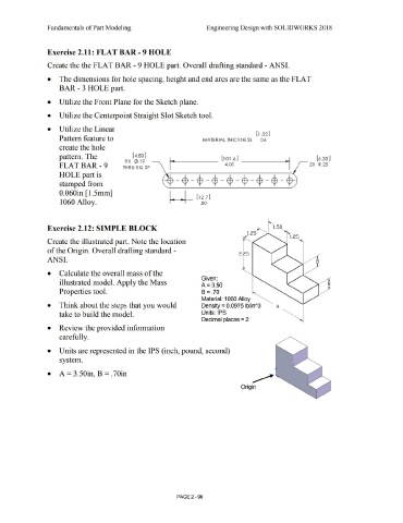
Exercise 2.11: FLAT BAR- 9 HOLE
Create the the FLAT BAR - 9 HOLE part. Overall drafting standard - ANSI.
• The dimensions for hole spacing, height and end arcs are the same as the FLAT
BAR - 3 HOLE part.
• Utilize the Front Plane for the Sketch plane.
• Utilize the Centerpoint Straight Slot Sketch tool.
• Utilize the Linear
[ 1 .52]
Pattern feature to MATERIAL THICK NE SS .06
create the hole
pattern. The [ 4.83] [6 .35]
9X 0 .19
FLATBAR-9 THRU EQ SP 2X R .25
HOLE part is
stamped from --$-$-$-$-$-$-$-~
0.060in [1.5mm]
1060 Alloy.
Exercise 2.12: SIMPLE BLOCK >-... 1.50
1.25- """
Create the illustrated part. Note the location
of the Origin. Overall drafting standard -
2.25
ANSI.
• Calculate the overall mass of the
Given:
illustrated model. Apply the Mass
A= 3.50
Properties tool. B = .70
Material: 1060 Alloy
• Think about the steps that you would Density= 0.0975 lb/inA3 A
take to build the model. Units: IPS
Decimal places = 2
• Review the provided information
carefully.
• Units are represented in the IPS (inch, pound, second)
system.
• A= 3.50in, B = .70in
...
Origin
PAGE2-96