
Page 173 - Subyek Computer Aided Design - [David Planchard] Engineering Design with SOLIDWORKS
P. 173
Engineering Design with SOLIDWORKS® 2018 Fundamentals of Part Modeling
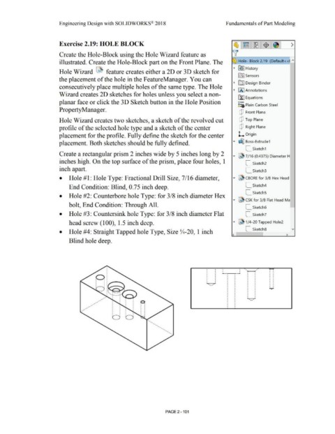
Exercise 2.19: HOLE BLOCK
Create the Hole-Block using the Hole Wizard feature as
illustrated. Create the Hole-Block part on the Front Plane. The ~~ Hole- Block 2.19 (Def au It <<!. "'
:~ ~ ~ I History
Hole Wizard ~ feature creates either a 2D or 3D sketch for
[0) Sensors
the placement of the hole in the FeatureManager. You can
~ [[II Design Binder
consecutively place multiple holes of the same type. The Hole
~ LA. I Annotations
Wizard creates 2D sketches for holes unless you select a non-
~ Equations
planar face or click the 3D Sketch button in the Hole Position o-
~:a Plain Carbon Steel
Property Manager.
Q Front Plane
Hole Wizard creates two sketches, a sketch of the revolved cut Q Top Plane
profile of the selected hole type and a sketch of the center Q Right Plane
placement for the profile. Fully define the sketch for the center L Origin
placement. Both sketches should be fully defined. ... ~ Boss-Extrude 1
L_ Sketch1
Create a rectangular prism 2 inches wide by 5 inches long by 2
... ~ 7 / 16 (0.4375) Diameter H
inches high. On the top surface of the prism, place four holes, 1 L_ Sketch2
inch apart. L_ Sketch3
• Hole # 1: Hole Type: Fractional Drill Size, 7 /16 diameter, ... ~ CBORE for 3/8 Hex Head
End Condition: Blind, 0.75 inch deep. L_ Sketch4
L_ SketchS
• Hole #2: Counterbore hole Type: for 3/8 inch diameter Hex
... @l CSK for 3/8 Flat Head Ma
bolt, End Condition: Through All.
L_ Sketch6 ~
• Hole #3: Countersink hole Type: for 3/8 inch diameter Flat L_ Sketch7
head screw (100), 1.5 inch deep. ... ~ 1/4-20 Tapped Hole2
L_ Sketch8 v
• Hole #4: Straight Tapped hole Type, Size lf4-20, 1 inch
< >
Blind hole deep.
' .
I I <I f' ' .
I j ' ( ' .
'----~
•
• ' .
• •
• ' .
' .
• ' .
•
. , •
·.- • I I I I
•
• .....
• •
•
•
•
•
•
•
, P. •
, , ' • • •
•
•
,• • ' • . ' •
, • • •
, • • • • •
• •
• •
• • • • •
• •
•
C) C)
•
• •
•
•
•
•
PAGE 2 - 101