
Page 170 - Subyek Computer Aided Design - [David Planchard] Engineering Design with SOLIDWORKS
P. 170
Fundamentals of Part Modeling Engineering Design with SOLIDWORKS 2018
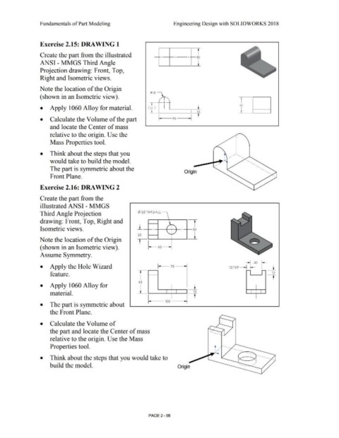
Exercise 2.15: DRAWING 1
1
Create the part from the illustrated so
ANSI - MMGS Third Angle _l
Projection drawing: Front, Top,
Right and Isometric views.
Note the location of the Origin
Rl S
(shown in an Isometric view).
t
+ 45
• Apply 1060 Alloy for material. ( 30 ) I __l_ !
t
10
• Calculate the Volume of the part l--- 90 -It
and locate the Center of mass
relative to the origin. Use the
Mass Properties tool.
• Think about the steps that you . . ' .
• •
#.
would take to build the model.
The part is symmetric about the
Origin
Front Plane.
Exercise 2.16: DRAWING 2
Create the part from the
illustrated ANSI - MMGS
Third Angle Projection ¢25 THRUALL '
drawing: Front, Top, Right and r
' .
J_ r I "
Isometric views. . • - 50
'" I ./
25 ' _l
Note the location of the Origin
(shown in an Isometric view). ~ 60
Assume Symmetry.
~30 ~
• Apply the Hole Wizard 10 TYP -1 f- I __l_
-
-
feature. I 1--- ---· I 12
60
• Apply 1060 Alloy for L _L
material. i I I 10 ! ' I
t
100
• The part is symmetric about
the Front Plane.
• Calculate the Volume of
. .
. . .
the part and locate the Center of mass :.-:r-. .. . .. .
.
--
'·-..
..
.... ~
.
.
•
.
relative to the origin. Use the Mass ; ....
.
.
•
.
.
•
Properties tool. . . . .. .. . . ..
.
L ··---.... . . . . . -........ .
.
. -..
• Think about the steps that you would take to . . ··-. ... . .. ·-.•
....
.
.
< -- ~;
'
' ...... - _,,,, '
build the model. Origin ------ ·-. ······ ... -
PAGE2 - 98