Page 174 - Subyek Computer Aided Design - [David Planchard] Engineering Design with SOLIDWORKS
P. 174

Fundamentals of Part Modeling                                                                                                                                 Engineering Design with SOLIDWORKS 2018


                                                Exercise 2.20: 30 SKETCH/HOLE WIZARD


                                                Create the part using the Hole Wizard feature. Apply the 3D


                                                sketch placement method as illustrated in the FeatureManager.


                                                Insert and dimension a hole on a cylindrical face.


                                                Copy and open Hole Wizard 2.20 from the Chapter 2 Homework


                                                folder.


                                                Note: With a 30 sketch, press the Tab key to move between


                                                planes.


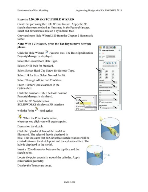
                                                                                                                                                                                                                                                                              ~ Hole Specification                                (i)

                                                Click the Hole Wizard  ~ Features tool. The Hole Specification                                                                                                                                                                ~  x


                                                PropertyManager is displayed.                                                                                                                                                                                                lJJ Type  U Positions


                                                Select the Counterbore Hole Type.                                                                                                                                                                                            Favorite                                          "'  "'


                                                Select ANSI Inch for Standard.                                                                                                                                                                                                         No Favorite Selected                v


                                                                                                                                                                                                                                                                             Hole Type
                                                Select Socket Head Cap Screw for fastener Type.                                                                                                                                                                                               00  m


                                                                                                                                                                                                                                                                            m  m                               1«Jb,

                                                Select 1/4 for Size. Select Normal for Fit.

                                                                                                                                                                                                                                                                            '[JJ   I  00                       tiD


                                                                                                                                                                                                                                                                            ,
                                                Select Through All for End Condition.                                                                                                                                                                                        Standard:                        ~


                                                                                                                                                                                                                                                                             ~AN-SI  1-nch--                              v

                                                Enter .100 for Head clearance in the                                                                                                                                                                                         Type:


                                                Options box.                                                                                                                                                                                                                 Socket Head Cap Screw                         v


                                                                                                                                                                                                                                                                             Hole Specifications                               "'

                                                Click the Positions Tab. The Hole Position                                                                                                                                                                                   Size:


                                                                                                                                                                                                                                                                                         --~
                                                                                                                                                                                                                                                                              1/4
                                                PropertyManager is displayed.

                                                                                                                                                                                                                                                                             Fit:
                                                                                                                                                                                                                                                                            --~ -

                                                                                                                                                                                                                                                                             Normal                                   ~
                                                Click the 3 D Sketch button.

                                                                                                                                                                                                                                                                              D Show custom sizing
                                                                                                                                                                                                              ~ 0.1
                                                SOLIDWORKS displays a 3D interface                                                                                                                                                                                           End Condition


                                                                                                                                                                                                              0 Near side  Head Clearance
                                                                                    .  ~                                                                                                                                                                                      ~ ]  Through All

                                                      . hh                                                             1.
                                                wit  t  e Point  xv  .(  too  active.


                                                   , ,/


                                                  -;Q~ When the Point tool is active,


                                                wherever you click you will create a point.


                                                Dimension the sketch.


                                                Click the cylindrical face of the model as


                                                illustrated. The selected face is displayed in


                                                blue. This indicates that an OnSurface sketch relations will be


                                                created between the sketch point and the cylindrical face. The


                                                hole is displayed in the model.


                                                Insert a .25in dimension between the top face and the


                                                sketch point.


                                                Locate the point angularly around the cylinder. Apply


                                                construction geometry.


                                                Display the Temporary Axes.


                                                                                                                                                                               PAGE 2 - 102
   169   170   171   172   173   174   175   176   177   178   179