
Page 175 - Subyek Computer Aided Design - [David Planchard] Engineering Design with SOLIDWORKS
P. 175
Engineering Design with SOLIDWORKS® 2018 Fundamentals of Part Modeling
Click the Line / Sketch tool. Note: 30 sketch is still activated.
Ctrl+click the top flat face of the model. This moves the red
space handle origin to the selected face. This also constrains any
new sketch entities to the top flat face. Note the mouse pointer
.
icon.
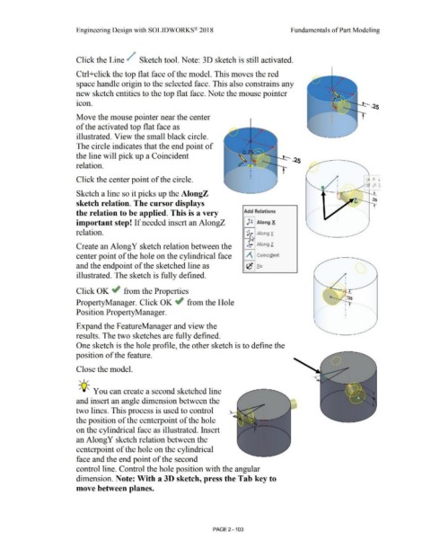
Move the mouse pointer near the center
of the activated top flat face as
illustrated. View the small black circle.
The circle indicates that the end point of
the line will pick up a Coincident ....... _
relation.
Click the center point of the circle.
Sketch a line so it picks up the AlongZ
sketch relation. The cursor displays
the relation to be applied. This is a very Add Relatjon_s
important step! If needed insert an AlongZ µ Along X
relation. Along Y.
t
Along l.
Create an Along Y sketch relation between the ~
center point of the hole on the cylindrical face /\ Coincident
and the endpoint of the sketched line as ',c Fix
illustrated. The sketch is fully defined.
Click OK ~ from the Properties
PropertyManager. Click OK ~ from the Hole
Position PropertyManager.
\
Expand the FeatureManager and view the
results. The two sketches are fully defined.
One sketch is the hole profile, the other sketch is to define the
position of the feature.
Close the model.
, ,/
-;Q~ You can create a second sketched line
and insert an angle dimension between the
two lines. This process is used to control
the position of the centerpoint of the hole
on the cylindrical face as illustrated. Insert
an Along Y sketch relation between the
centerpoint of the hole on the cylindrical
face and the end point of the second
control line. Control the hole position with the angular
dimension. Note: With a 30 sketch, press the Tab key to
move between planes.
PAGE 2 - 103