
Page 176 - Subyek Computer Aided Design - [David Planchard] Engineering Design with SOLIDWORKS
P. 176
Fundamentals of Part Modeling Engineering Design with SOLIDWORKS 2018
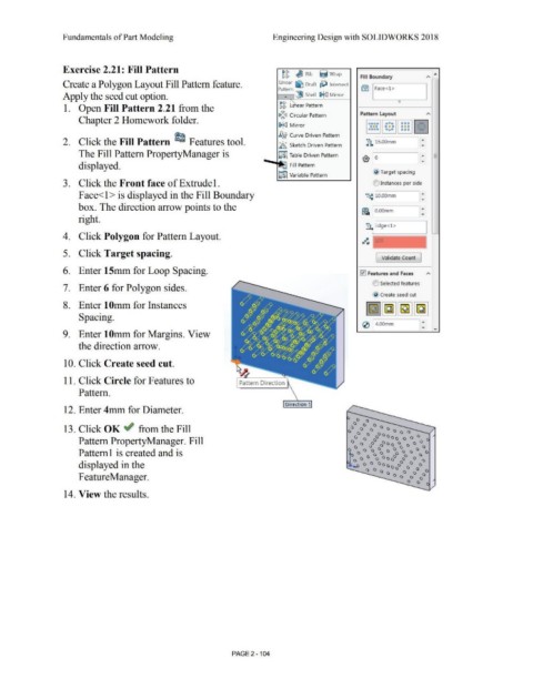
Exercise 2.21: Fill Pattern
~g ~ Rib ijJ Wrap •
Fill Boundary "' ,--,
Create a Polygon Layout Fill Pattern feature. Linear ~ Draft ~ Intersect
Pattern @:) Face<l >
Apply the seed cut option. • (!9J Shell !}iii;] Mirror
~g ear Pattern 0
1. Open Fill Pattern 2.21 from the
li,li~<:J Circular Pattern Pattern Layout ,..
Chapter 2 Homework folder.
ooo
~fCJ Mirror 0000 0 0 0 000
0 0 0
0 0 0
0000 OoO OGG
~ Curve Driven Pattern
• •
2. Click the Fill Pattern ~ Features tool. • .Ji+ 15.00mm
;.~~ Sketch Driven Pattern
The Fill Pattern PropertyManager is J;i§ Table Driven Pattern -
-
€) 6 -
displayed. ....._...,. ~ Fill Pattern
~
~ Target spacing
~ Variable Pattern
3. Click the Front face of Extrude 1. O Instances per side
Face<l > is displayed in the Fill Boundary •::; 10.00mm
box. The direction arrow points to the ..
~=·(~ O.OOmm
....
right.
-
•:: ~dge<l>
4. Click Polygon for Pattern Layout.
5. Click Target spacing.
[ Validate Count ]
6. Enter 15mm for Loop Spacing. 10 Features and Faces
-
U Selected features
7. Enter 6 for Polygon sides.
@ create seed cut
8. Enter 1 Omm for Instances
Spacing.
..... ...
(2) 4.00mm
9. Enter lOmm for Margins. View
the direction arrow.
10. Click Create seed cut.
11. Click Circle for Features to Pattern Direction
Pattern.
Direction 1 •
12. Enter 4mm for Diameter.
13. Click OK ~ from the Fill / -
Pattern PropertyManager. Fill
Patternl is created and is
displayed in the
F eatureManager.
14. View the results.
PAGE 2 - 104