
Page 181 - Subyek Computer Aided Design - [David Planchard] Engineering Design with SOLIDWORKS
P. 181
Engineering Design with SOLIDWORKS® 2018 Fundamentals of Assembly Modeling
Project 3 - Fundamentals of Assembly Modeling
Project Objective
($)!~ 1~1$ 1~1 >
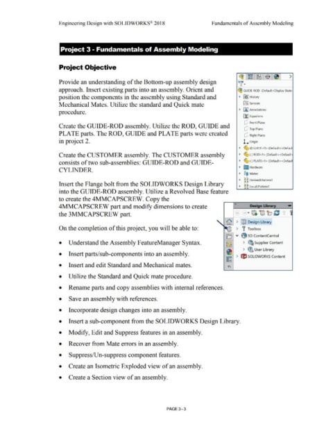
Provide an understanding of the Bottom-up assembly design v-
approach. Insert existing parts into an assembly. Orient and ~ GUIDE-ROD (Default<Display State
position the components in the assembly using Standard and • B!> I History
Mechanical Mates. Utilize the standard and Quick mate lfrJ Sensors
• IA] Annotations
procedure.
[f:J Equations
dJ Front Plane
Create the GUIDE-ROD assembly. Utilize the ROD, GUIDE and
dJ Top Plane
PLATE parts. The ROD, GUIDE and PLATE parts were created dJ Right Plane
in project 2. L o rigin
• ~ (f)GUIDE<1>(Default<<Defaul
Create the CUSTOMER assembly. The CUSTOMER assembly • ~ (-) ROD<1> (Default<<Default·
consists of two sub-assemblies: GUIDE-ROD and GUIDE- • ~ (-) PLATE<1 > (Default<<Defaul
• [J Hardware
CYLINDER.
• ®@ Mates
• ~ g DerivedLPattern1
Insert the Flange bolt from the SOLIDWORKS Design Library
• ~ g LocalLPattern1
into the GUIDE-ROD assembly. Utilize a Revolved Base feature
to create the 4MMCAPSCREW. Copy the
«
4MMCAPSCREW part and modify dimensions to create Design Library
the 3MMCAPSCREW part.
-- > tMJ Design Library
On the completion of this project, you will be able to: ) f Toolbox
!-----..
IEj v ~ 30 ContentCentral
• Understand the Assembly FeatureManager Syntax. ~ > ~ Supplier Content
~ > ~ User Library
• Insert parts/sub-components into an assembly.
~ > t1'J SOLIDWORKS Content
• Insert and edit Standard and Mechanical mates. ~
• Utilize the Standard and Quick mate procedure.
• Rename parts and copy assemblies with internal references.
• Save an assembly with references.
• Incorporate design changes into an assembly.
• Insert a sub-component from the SOLIDWORKS Design Library.
• Modify, Edit and Suppress features in an assembly.
• Recover from Mate errors in an assembly.
• Suppress/Un-suppress component features.
• Create an Isometric Exploded view of an assembly.
• Create a Section view of an assembly.
PAGE3 - 3