
Page 185 - Subyek Computer Aided Design - [David Planchard] Engineering Design with SOLIDWORKS
P. 185
Engineering Design with SOLIDWORKS® 2018 Fundamentals of Assembly Modeling
GUIDE-ROD assembly ~1~ 1~]$ 1~1 >
~~
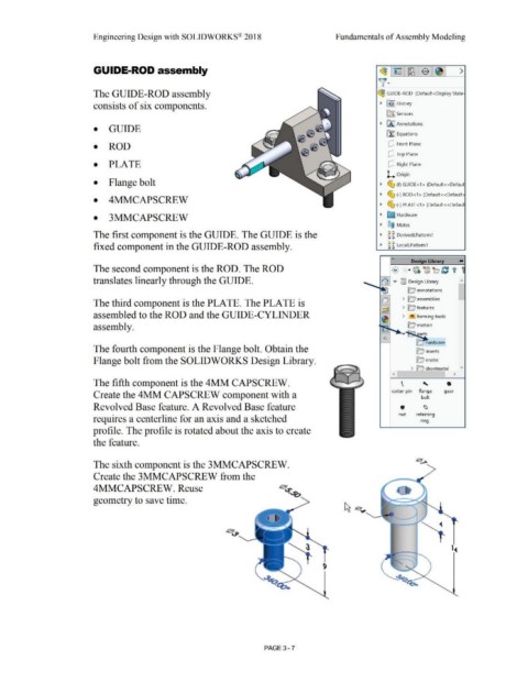
The GUIDE-ROD assembly ~ GUIDE-ROD (Default<Display State·
consists of six components. • ~ ] History
[aJ Sensors
• IA] Annotations
• GUIDE
rt:J Equations
• ROD dJ Front Plane
dJ Top Plane
• PLATE dJ Right Plane
L Origin
• Flange bolt • ~ (f) GUIDE<1 > (Default<<Defaul
• ~ (·) ROD<1 > (Default<<Default:
• 4MMCAPSCREW
• ~ (·) PLATE<1 > (Default<<Defaul
• 3MMCAPSCREW • Q Hardware
• ®@ Mates
The first component is the GUIDE. The GUIDE is the • ~ ~ DerivedLPattern1
fixed component in the GUIDE-ROD assembly. • ~ ~ LocalLPattern1
«
Design Library
The second component is the ROD. The ROD
translates linearly through the GUIDE.
O annotations
> D assemblies
The third component is the PLATE. The PLATE is
> Q features
assembled to the ROD and the GUIDE-CYLINDER > ~ forming tools
assembly. Q motion
v
The fourth component is the Flange bolt. Obtain the Q inserts
Flange bolt from the SOLIDWORKS Design Library. Q knobs
- > n sheetmetal "
< >
The fifth component is the 4MM CAPSCREW. ' 0
\
cotter pin flange gear
Create the 4MM CAPSCREW component with a bolt
Revolved Base feature. A Revolved Base feature . ~
nut retaining
requires a centerline for an axis and a sketched nng
profile. The profile is rotated about the axis to create
the feature.
The sixth component is the 3MMCAPSCREW.
Create the 3MMCAPSCREW from the
4MMCAPSCREW. Reuse
geometry to save time.
1,t
PAGE3 - 7