
Page 190 - Subyek Computer Aided Design - [David Planchard] Engineering Design with SOLIDWORKS
P. 190
Fundamentals of Assembly Modeling Engineering Design with SOLIDWORKS® 2018
The ROD part icon is displayed in the Open
documents text box. The mouse pointer
displays the ROD component when positioned
inside the GUIDE-ROD Graphics window.
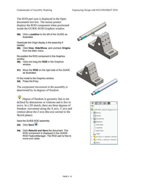
28) Click a position to the left of the GUIDE as
illustrated. •
• •
Deactivate the Origin display in the assembly if •
needed. • •
29) Click View, Hide/Show, and uncheck Origins
from the Main menu.
Re-position the ROD component in the Graphics
window.
30) Click and drag the ROD in the Graphics
window.
31) Move the ROD on the right side of the GUIDE
as illustrated.
Fit the model to the Graphics window.
32) Press the f key. 0
The component movement in the assembly is
determined by its degrees of freedom.
, ,/
-;Q~ Degree of freedom is geometry that is not
defined by dimensions or relations and is free to
~ ~ ~ $ ~ >
move. In a 20 sketch, there are three degrees of
~ ·
freedom: movement along the X axis, Y axis and
~ GUIDE-ROD (Default<Display State-1:
rotation about the Z axis ( the axis normal to the
~ ~ I History
Sketch plane). lfl] Sensors
~ fA l Annotations
Save the GUIDE-ROD assembly.
~ Equations
33) Click Save [ii_ Q Front Plane
Q Top Plane
34) Click Rebuild and Save the document. The Q Right Plane
ROD component is displayed in the GUIDE- L Origin
ROD FeatureManager. The ROD part is free to ~ ~ (f) GUIDE<1 > (Default<<Default>
move and rotate.
~ ~ (-) ROD<1 > (Default< <Default>_
®@ Mates
PAGE 3 - 12