Page 191 - Subyek Computer Aided Design - [David Planchard] Engineering Design with SOLIDWORKS
P. 191

Engineering Design with SOLIDWORKS® 2018                                                                                                                                               Fundamentals of Assembly Modeling


                                                                        Review the FeatureManager Syntax.


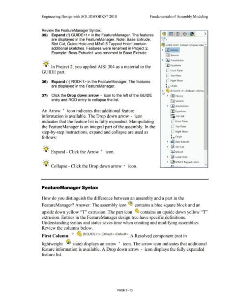
                                                                        35)  Expand (f) GUIDE<1 > in the FeatureManager. The features                                                                                                                                               ~~~ $ ~                                                                 >

                                                                                                                                                                                                                                                                                   v·
                                                                                        are displayed in the FeatureManager. Note: Base Extrude,


                                                                                        Slot Cut, Guide Hole and M3x0.5 Tapped Hole1  contain                                                                                                                                     ~ GUIDE-ROD  (Default<Display State  "


                                                                                        additional sketches. Features were renamed in  Project 2.                                                                                                                                                 History I
                                                                                                                                                                                                                                                                                    ~  [~
                                                                                        Example: Boss-Extrude1 was renamed to Base Extrude.

                                                                                                                                                                                                                                                                                          ifl:I Sensors


                                                                          , ,,,.                                                                                                                                                                                                    ~  [A] Annotations


                                                                          -;Q~ In Project 2, you applied AISI 304 as a material to the                                                                                                                                                    ~ Equations


                                                                        GUIDE part.                                                                                                                                                                                                        dJ  Front Plane


                                                                                                                                                                                                                                                                                           dJ  Top Plane


                                                                        36)  Expand (-) ROD<1 > in the FeatureManager. The features                                                                                                                                                        dJ  Right Plane


                                                                                        are displayed in the FeatureManager.                                                                                                                                                              L  Origin


                                                                                                                                                                                                                                                                                   ~ ~ (f) GUIDE<1 > (Default<<Defau


                                                                        37)  Click the Drop down arrow ...  icon to the left of the GU IDE                                                                                                                                                   ~  lb I History


                                                                                        entry and ROD entry to collapse the list.                                                                                                                                                                 ifi:j Sensors


                                                                                                                                                                                                                                                                                             ~  IA) Annotations


                                                                        An Arrow  •  icon indicates that additional feature                                                                                                                                                                       [l:J Equations


                                                                                                                                                                                                                                                                                                  o-
                                                                        information is available. The Drop down arrow ...  icon                                                                                                                                                                   ~:a AISI 304


                                                                        indicates that the feature list is fully expanded. Manipulating                                                                                                                                                             dJ  Front Plane


                                                                       the FeatureManager is an integral part of the assembly. In the                                                                                                                                                               dJ  Top Plane


                                                                        step-by-step instructions, expand and collapse are used as                                                                                                                                                                  dJ  Right Plane


                                                                        follows:                                                                                                                                                                                                                  L  Origin


                                                                                                                                                                                                                                                                                             ~  ~ Base Extrude

                                                                          , 1,,.
                                                                                                                                                                                                                                                                                             ~  ~ Slot Cut


                                                                                                                                                                                    •
                                                                          -;Q~ Expand - Click the Arrow  •                                                                          lCOn.                                                                                                         GJli;J M irror1


                                                                                                                                                                                                                                                                                             ~  ~ Guide Hole
                                                                          , 1,,.

                                                                                                                                                                                                                                                                                             ~  ~ M3x0.5 Tapped Hole1

                                                                                                                                                                                                                           •
                                                                          -;Q~ Collapse - Click the Drop down arrow ....                                                                                                  lCOn.                                                        -           ~ f:l  . - ·-· ___ ..


                                                                        FeatureManager Syntax


                                                                        How do you distinguish the difference between an assembly and a part in the


                                                                        FeatureManager? Answer: The assembly icon ~  contains a blue square block and an


                                                                       upside down yellow ''T'' extrusion. The part icon  ~ contains an upside down yellow ''T''


                                                                        extrusion. Entries in the F eatureManager design tree have specific definitions.


                                                                       Understanding syntax and states saves time when creating and modifying assemblies.


                                                                        Review the columns below.


                                                                                                                                                                      1
                                                                        First Column:  ~  ~ (f) GUIDE< > (Default<<Default>_  A Resolved component (not in


                                                                        lightweight  ~ state) displays an arrow  •  icon. The arrow icon indicates that additional


                                                                        feature information is available. A Drop down arrow ...  icon displays the fully expanded


                                                                        feature list.


                                                                                                                                                                                                        PAGE 3- 13
   186   187   188   189   190   191   192   193   194   195   196