Page 193 - Subyek Computer Aided Design - [David Planchard] Engineering Design with SOLIDWORKS
P. 193

Engineering Design with SOLIDWORKS® 2018                                                                                                           Fundamentals ofAsse1nbly Modeling


                                                                                                                                       1
                                                         Third Column:  ~  ~ (f) GUIDE< > (Default<<Default>._ The part is fixed (f). You can fix the


                                                         position of a component so that it cannot move with respect to the assembly Origin. By


                                                          default, the frrst part in an assembly is fixed; however, you can float it at any time.


                                                         It is recommended that at least one assembly component is either fixed or mated to the


                                                          assembly planes or Origin. This provides a frame of reference for all other mates and


                                                         helps prevent unexpected movement of components when mates are added. The


                                                          Component Properties are:


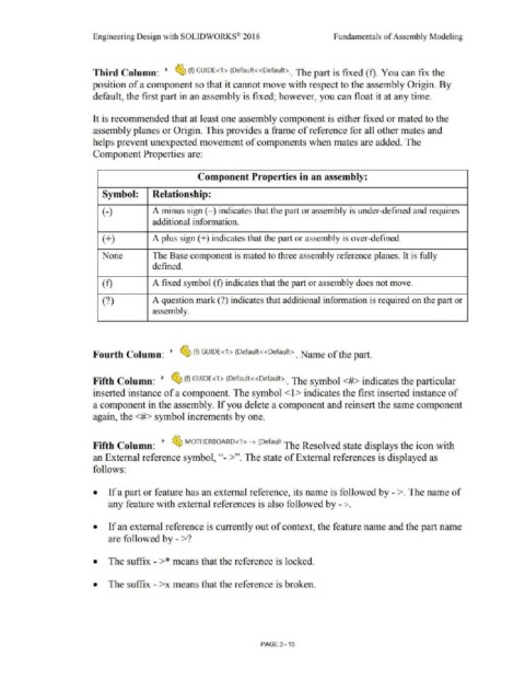
                                                                                                                          Component Properties in an assembly:


                                                               Symbol:                        Relationship:


                                                               (-)                            A minus sign(-) indicates that the part or assembly is under-defined and requires


                                                                                              additional information.


                                                               (+)                            A plus sign(+) indicates that the part or assembly is over-defined.


                                                               None                           The Base component is mated to three assembly reference planes. It is fully


                                                                                              defined.


                                                               (f)                            A fixed symbol (f) indicates that the part or assembly does not move.


                                                               (?)                            A question mark (?) indicates that additional information is required on the part or


                                                                                              assembly.


                                                          Fourth Column:  ~  ~ (f)  GUIDE<1> (Default<<Default>._  Name of the part.


                                                                                                                                     1
                                                         Fifth Column:  ~  ~ (f) GUIDE< > (Default<<Default>._ The symbol<#> indicates the particular


                                                          inserted instance of a component. The symbol < l> indicates the first inserted instance of


                                                          a component in the assembly. If you delete a component and reinsert the same component


                                                          again, the <#> symbol increments by one.


                                                                                                                                                                           1
                                                          Fifth Column:  ~  ~ MOTHERBOARD<l >  -> (Defaul The Resolved state displays the icon with


                                                          an External reference symbol,''- >''. The state of External references is displayed as


                                                          follows:


                                                          •  If a part or feature has an external reference, its name is followed by - >. The name of


                                                                   any feature with external references is also followed by - >.


                                                          •  If an external reference is cu.rrently out of context, the feature name and the part name


                                                                   are followed by - >?


                                                          •  The suffix - >* means that the reference is locked.


                                                          •  The suffix - >x means that the reference is broken.


                                                                                                                                                                PAGE3-15
   188   189   190   191   192   193   194   195   196   197   198