
Page 198 - Subyek Computer Aided Design - [David Planchard] Engineering Design with SOLIDWORKS
P. 198
Fundamentals of Assembly Modeling Engineering Design with SOLIDWORKS® 2018
I Activity: GUIDE-ROD Assembly - Mate the ROD Component
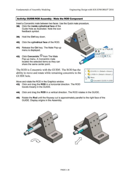
Insert a Concentric mate between two faces. Use the Quick mate procedure.
38) Click the inside cylindrical face of the
Guide Hole as illustrated. Note the icon
feedback symbol.
39) Hold the Ctrl key down. • •
• •
40) Click the cylindrical face of the ROD. • •
41) Release the Ctrl key. The Mate Pop-up
menu is displayed.
42) Click Concentric @ from The Mate
Pop-up menu. A Concentric mate
locates the selected items so they can
share the same center point.
The ROD is Concentric with the GUIDE. The ROD has the
~ ~ (t) GUIDE<1 > (Default< <Default>_
ability to move and rotate while remaining concentric to the
~ ~ (-) ROD<1 > (Default<<Default> _C,
GUIDE hole.
~ ®@ Mates
@ concentric1 (GUIDE<1 >,ROD·
Move and rotate the ROD in the Graphics window.
43) Click and drag the ROD in a horizontal direction. The ROD
travels linearly in the GUIDE.
44) Click and drag the ROD in a vertical direction. The ROD rotates in the GUIDE.
45) Rotate the Rod until the Keyway cut is approximately parallel to the right face of the
GUIDE. Display origins in the Assembly.
PAGE 3- 20