
Page 200 - Subyek Computer Aided Design - [David Planchard] Engineering Design with SOLIDWORKS
P. 200
Fundamentals of Assembly Modeling Engineering Design with SOLIDWORKS® 2018
The ROD mates reflect the physical constraints in the GUIDE-ROD assembly. The ROD
is under defined, indicated by a minus sign (-).
The Concentric mate allows the ROD to translate freely in the Z direction through the
Guide Hole. The Parallel Mate prevents the ROD from rotating in the Guide Hole.
The GUIDE part icon is displayed with no color in the FeatureManager to reflect the
Hide state.
GUIDE-ROD Assembly· Mate the PLATE Component
Recall the initial design constraints.
• The ROD is fastened to the PLATE.
• The PLATE part mounts to the GUIDE-CYLINDER PISTON PLATE part.
Apply the Rotate Component ~ tool to position the PLATE before applying the Mates.
I Activity: GUIDE-ROD Assembly - Mate the PLATE Component
Insert the PLATE component into the assembly from the PROJECTS folder.
-
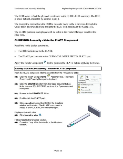
58) Click the Insert Components bc@3 Assembly tool. The Insert b(!E ~ <,,: 1
Component PropertyManager is displayed. Insert Mate Component Lir
Components Preview Wrndo\
...
59) Click the BROWSE button from the Open documents box. " -
b~ lns~rt Components I}
Note: In some SOLIDWORKS versions, the Open document ~ >--
box opens. New Part
~
New Assembly
~ Copy with Mates
60) Browse to the PROJECTS folder.
61) Double-click the PLATE part.
62) Click a position behind the ROD in the Graphics
window as illustrated. The PLATE component is
added to the GUIDE-ROD FeatureManager.
Display an Isometric view.
63) Click Isometric view ~ .
Fit the model to the Graphics window.
64) Press the f key. View the results in the Graphics
window.
PAGE 3 - 22